Safety injection tank with gravity driven fluidic device

a fluid injection tank and safety technology, applied in nuclear engineering, greenhouse gas reduction, nuclear elements, etc., can solve the problems of reducing the accuracy of thermal hydraulic analysis of the reactor system, unable to efficiently estimate the turndown ratio between the maximum and minimum flow rate, and difficulty in controlling the turndown ratio. , to achieve the effect of preventing an early injection of nitrogen gas, reducing the effective volume of discharged emergency core cooling water, and easy control of the turndown ratio

Active Publication Date: 2009-11-12
KOREA HYDRO & NUCLEAR POWER CO LTD
View PDF0 Cites 11 Cited by
  • Summary
  • Abstract
  • Description
  • Claims
  • Application Information

AI Technical Summary

Benefits of technology

[0027]The safety injection tank having the above-mentioned gravity-driven fluidic device according to the present invention is advantageous as follows. Unlike a conventional fluidic device, in which the inlet port of the vertical pipe has an open structure, so that nitrogen gas may be early injected through the open inlet port of the vertical pipe and discharged outside the safety injection tank, the upper open port of the vertical pipe of the gravity-driven fluidic device according to the present invention is configured to be selectively opened or closed both by the vertical weight of the vertically movable water tub and the restoring force of the spring, so that the gravity-driven fluidic device can prevent an early injection of nitrogen gas. Thus, the safety injection tank having the gravity-driven fluidic device according to the present invention is advantageous in that it is possible to easily control the turndown ratio of the emergency core cooling water, which is required to design a reactor system provided against a large break loss-of-coolant accident (LBLOCA), and it is possible to prevent an early injection of nitrogen gas.
[0028]Further, unlike the conventional fluidic device, in which a downward discharge flow path is not formed in the lower hemispherical surface, so that the emergency core cooling water contained in the fluidic device at a portion below the upper surface of the fluidic device cannot be discharged from the safety injection tank, the safety injection tank of the present invention is provided with a low flow inlet port at a location around the lower hemispherical surface, thus completely discharging the emergency core cooling water contained in the fluidic device at a portion below the lower hemispherical surface. Therefore, the present invention can increase the effective volume of discharged emergency core cooling water used for cooling a nuclear reactor. Thus, the present invention increases low flow injection time and retards the reduction in the core cooling water level for the nuclear reactor. When the reduction in the core cooling water level is prevented during the low flow injection time period (during LBLOCA reflood phase), it is possible to prevent a quick increase in the core temperature of a nuclear reactor, thus improving the safety of the nuclear reactor.

Problems solved by technology

However, the fluidic device disclosed in the Korean Patent No. 369247 is problematic in that the device has a complicated inner structure, as shown in the cross-sectional views of (a) and (b) of FIG. 1, and the characteristics thereof may be easily changed according to a change in the swirling direction of the vortex, a surface area ratio and a relative angle between respective discharge lines, so that it is very difficult to estimate the characteristics of a turndown ratio using the surface area ratio between the high flow inlet port and the low flow inlet port.
However, the fluidic device shown in FIG. 1 cannot efficiently estimate the turndown ratio between the maximum and minimum flow rates.
Another problem of the fluidic device shown in FIG. 1 resides in that the large flow supply line inlet port 20 is exposed to the nitrogen gas in the safety injection tank 10 during a low flow injection mode, as shown in FIG. 2 schematically illustrating both a turndown point and a time to early inject the nitrogen gas when the injected flow rate is changed from a high flow rate to a low flow rate, so that an early injection of nitrogen gas, in which the nitrogen gas is early injected into the reactor system along with the emergency core cooling water, may occur during the low flow injection mode.
When the nitrogen gas is early injected into the reactor system as described above, the nitrogen gas may disturb condensation of steam in the reactor system and reduces the precision of thermal hydraulic analysis of the reactor system, thus causing some problems in the reactor system.
However, each of the above-mentioned prior art safety injection tanks has a structure, which cannot avoid the early injection of nitrogen gas.
However, the buoyant plate made of a material with low specific weight is almost impossible to cope with a desired life soundness, which requires the buoyant plate to endure without damage for 40-60 years that are the typical life spans of nuclear power plates.
Further, when the fluidic device is continuously kept in a standby state without being operated for a lengthy period of time, the buoyant plate may be fixed to the inlet port of the vertical pipe and fails to start its operation, so that it is very difficult to use the buoyant plate in a practical safety injection tank.

Method used


Image

  • Safety injection tank with gravity driven fluidic device
  • Safety injection tank with gravity driven fluidic device
  • Safety injection tank with gravity driven fluidic device

Examples


Embodiment Construction

[0042]Reference will now be made in greater detail to a preferred embodiment of the invention, an example of which is illustrated in the accompanying drawings. Wherever possible, the same reference numerals will be used throughout the drawings and the description to refer to the same or like parts. Further, in the flowing description, a detailed description for the well-known construction and well-known function thereof will be omitted in an effort to avoid confusion of the gist of the present invention.

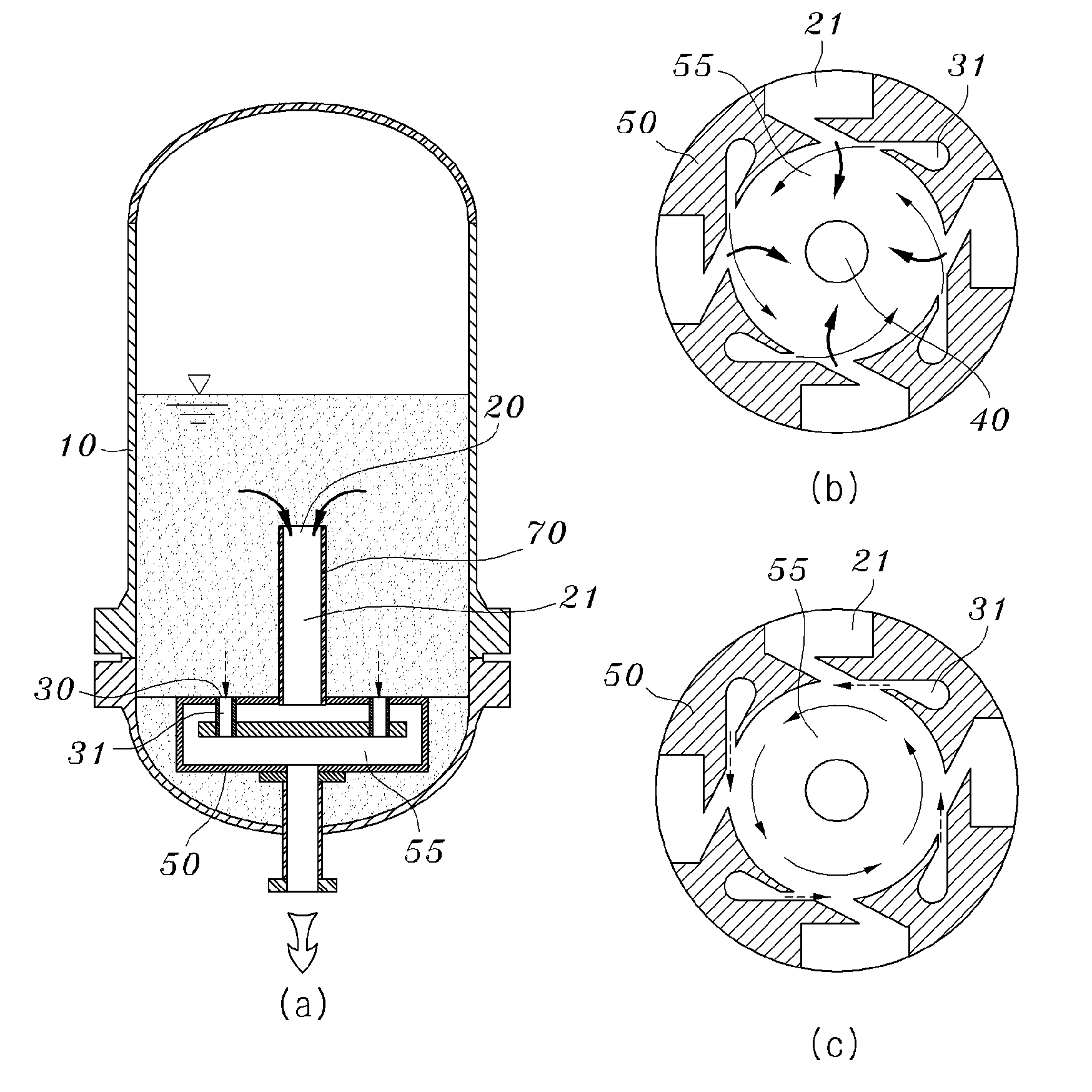
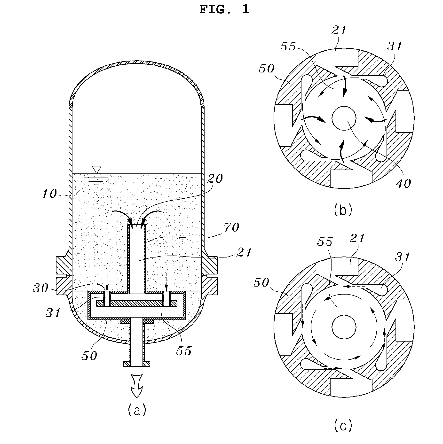
[0043]First, the operational theory of a safety injection tank 100 having a gravity-driven fluidic device 130 according to the present invention, in which the gravity-driven fluidic device 130 completely passively controls a high flow inlet port 123 in response to a variation in the water level of the emergency core cooling water (ECCW) 112 inside the tank 100, will be described in brief hereinbelow.

[0044]FIG. 4A is a sectional view of the safety injection tank 100 having the gravity...


PUM


Abstract

A safety injection tank, used for quickly injecting emergency core cooling water (ECCW) to a reactor vessel in the case of a cold leg large break accident (CLLBA) in a pressurized water reactor (PWR), is disclosed. The safety injection tank has a gravity-driven fluidic device configured to efficiently change the ECCW injection mode from a high flow injection mode to a low flow injection mode. The gravity-driven fluidic device includes a spring placed in the upper end of the vertical pipe, and a vertically movable water tub placed on the spring so as to be movable in a vertical direction. When ECCW contained in the pressure vessel is discharged and the water level is reduced lower than the height of the tub, the tub is moved downwards such that the lower surface thereof comes into contact with the vertical pipe and closes the high flow inlet port.

Description

BACKGROUND OF THE INVENTION[0001]1. Field of the Invention[0002]The present invention relates, in general, to a safety injection tank used for quickly injecting emergency core cooling water (ECCW) to a reactor vessel in the case of a cold leg large break accident (CLLBA) in a pressurized water reactor (PWR) and, more particularly, to a technique related to a fluidic device configured to efficiently execute the transition of ECCW injection mode from a high flow injection mode in an early stage of the CLLBA to a low flow injection mode in a latter stage of the CLLBA. Particularly, the present invention relates to a technique of executing the transition of ECCW injection mode from a high flow injection mode to a low flow injection mode using a gravity-driven fluidic device, installed in the safety injection tank, as time goes by after operation of the safety injection tank.[0003]2. Description of the Related Art[0004]Pressurized water reactors (PWR) must be designed, constructed and op...

Claims


Application Information

Patent Timeline
Patent Type & Authority Applications(United States)
IPC IPC(8): G21C9/00
CPCY02E30/32G21C15/18Y02E30/30G21C15/00G21C9/012
Inventor KWON, TAE-SOONCHU, IN-CHULSONG, CHUL-HWABAEK, WON-PIL
Owner KOREA HYDRO & NUCLEAR POWER CO LTD
Why Eureka
Try Eureka