
Sliding restraint stent delivery systems

a stent and restraint technology, applied in the field of medical devices and methods, can solve the problems of poor placement, inability to scale the system, lack of space efficiency in the design of the delivery system, etc., and achieve the effect of convenient “locking” the system and facilitating the lock-down function

Inactive Publication Date: 2009-11-12
BIOSENSORS INT GROUP
View PDF105 Cites 1 Cited by
  • Summary
  • Abstract
  • Description
  • Claims
  • Application Information

AI Technical Summary

Benefits of technology

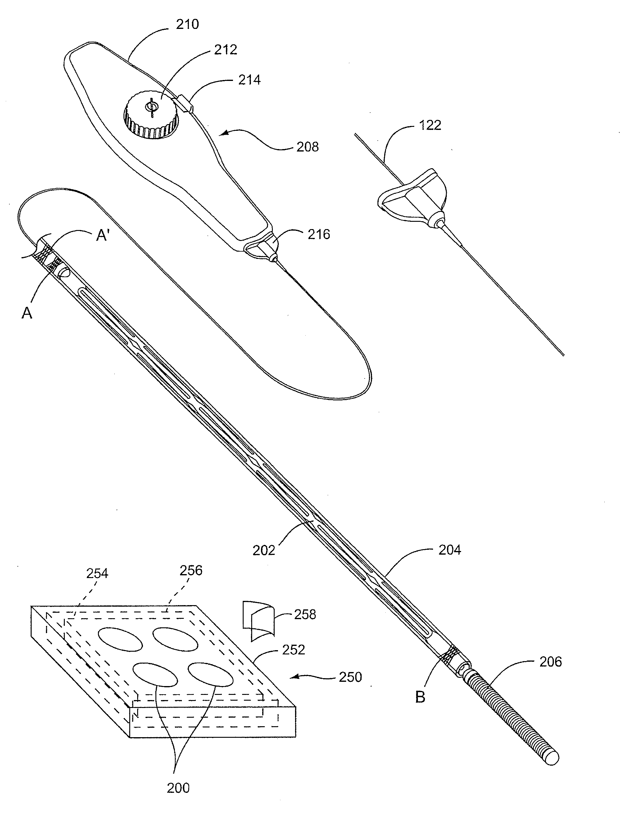
[0013]The present invention offers a high-precision stent placement delivery system, allowing a user to conveniently “lock-down” the system, if desired; and deliver a stent thus set in place. The system includes a stent and a delivery guide for carrying the stent to a treatment site and releasing the stent at that point. To facilitate the lock-down function, the delivery guide is configured such that it is actuated by a member interior to an outer sleeve onto which the hemostatic valve attached or connected to a catheter (e.g., a microcatheter or balloon catheter) can be collapsed. The inner member may be a core member (i.e., filling the center of or being coaxial with the sleeve) or one of a number of inner members.
[0014]The delivery guide further employs a distal restraint that holds the stent in a collapsed configuration in an undeployed state at a distal end portion of the delivery device. Actuation of the interior member (e.g., by withdrawing the same or by a physical shortening, such as by a heat-activated shape memory plastic or alloy wire) at a proximal end of the delivery system deploys the stent by way of withdrawal or retraction of the distal restraint from about the stent. In doing so, the restraint holding the stent or a connection thereto may pass from the outside of the delivery device to inside its body. Such an approach facilitates a low-profile delivery device that does not change in diameter during use.
[0021]Where the systems are adapted for use in small and / or tortuous anatomy, each of the above-referenced optional performance characteristics of the device offers great potential benefit. In the first instance, the adaptation so the distal end of the device does not increase in Its overall diameter from pre-deployment to post-deployment allows for the use of a closely-sized delivery catheter. An example of such a small delivery lumen is that a balloon catheter—one such means of delivery as advantageously employed in connection with the present invention. Details of such a mode of deployment is presented in U.S. patent application Atty. Docket No. CRMD-003, entitled “Balloon Catheter Lumen Based Stent Delivery Systems,” filed Dec. 24, 2003 and incorporated herein by reference in its entirety. Also, by avoiding delivery device distal diameter increase risk of embolizing vulnerable plaque may be decreased. Still further, the substantially constant system distal diameter helps avoid unintended additional vessel occlusion during a procedure.

Problems solved by technology

Problems encountered with known systems include drawbacks ranging from failure to provide means to enable precise placement of the subject prosthetic, to a lack of space efficiency in delivery system design.
Poor placement hampers stent efficacy.
Space inefficiency in system design prohibits scaling the systems to sizes as small as necessary to enable difficult access or small-vessel procedures (i.e., in tortuous vasculature or vessels having a diameter less than 3 mm, even less than 2 mm).
Though elegant in design, the system fails to offer desired functional characteristics.
Particularly, such a system is prone to misuse when a physician who is not intimately familiar with the hardware retracts or pushes the wrong one of the stent abutting member or the sheath in an effort to free the stent.
Even when not misused, simple sheath systems present issues with precise stent placement stemming from the fact that the sheath cannot be locked-down at the proximal end of an access catheter (e.g., at a hemostatic valve) while deploying the stent.
As a result, it is difficult to prevent inadvertent axial movement of the stent.
Such forward movement complicates stent placement and ma cause vessel injury due to the leading edges of the stent scraping against (producing “skid marks”), or even perforating the vessel wall.
However, careful actuation of a sheath-based delivery system will not ensure precise stent placement.
If not, slack in the delivery system either outside or inside of the patient can result in deploying the stent beyond the target site.
While FIGS. 4-7 of the '007 patent do disclose an alternative embodiment not prone to the forward stent / tip wandering as described above, the embodiment is not believed amenable to or adaptable for use in reaching very small, largely occluded or highly tortuous vasculature of the type described above.

Method used


Image

  • Sliding restraint stent delivery systems
  • Sliding restraint stent delivery systems
  • Sliding restraint stent delivery systems

Examples


Embodiment Construction

[0053]Before the present invention is described in detail, it is to be understood that this invention is not limited to particular variations set forth and may, of course, vary. Various changes may be made to the invention described and equivalents may be substituted without departing from the true spirit and scope of the invention. In addition, many modifications may be made to adapt a particular situation, material, composition of matter, process, process act(s) or step{s), to the objective(s), spirit or scope of the present invention. All such modifications are intended to be within the scope of the claims made herein.

[0054]Methods recited herein may be carried out in any order of the ‘recited events which is logically possible, as well as the recited order of events. Furthermore, where a range of values is provided, it is understood that every intervening value, between the upper and lower limit of that range and any other stated or intervening value in that stated range is enco...


PUM


Abstract

Medical device and methods for delivery or implantation of prostheses within hollow body organs and vessels or other luminal anatomy are disclosed. The subject technologies may be used in the treatment of atherosclerosis in stenting procedures. For such purposes, a self-expanding stent may be deployed in connection with an angioplasty procedure with a sliding restraint based delivery system adapted for simplified use. In the system, the sliding restraint is sized, in coordination with a fixed sleeve accepting a core wire to actuate the restraint to effect an anchoring function with the sleeve so that the stent is not inadvertently advanced during deployment.

Description

CROSS-REFERENCES TO RELATED APPLICATIONS[0001]This application is a continuation of U.S. patent application Ser. No. 10 / 792,684 (Attorney Docket No. 022037-000140US), filed on Mar. 2, 2004, the full disclosure of which is incorporated herein by reference.BACKGROUND OF THE INVENTION[0002]The present invention relates generally to medical devices and methods. More particularly, it relates to delivery systems for implanting prostheses within hollow body organs and vessels or other luminal anatomy.[0003]Implants such as stents and occlusive coils have been used in patients for a wide variety of reasons. One of the most common “stenting” procedures is carried out in connection with the treatment of atherosclerosis, a disease which result in a narrowing and stenosis of body lumens; such as the coronary arteries. At the site of the narrowing (i.e., the site of a lesion) a balloon is typically dilatated in an angioplasty procedure to open the vessel. A stent is set in apposition to the inte...

Claims


Application Information

Patent Timeline
Patent Type & Authority Applications(United States)
IPC IPC(8): A61F2/06A61F2/84A61F2/90
CPCA61F2/91A61F2002/9665A61F2/95
Inventor GEORGE, WILLIAM R.CHANG, JEAN C.TON, DAI T.DE BEER, NICHOLAS C.NIKOLCHEV, JULIANBECKING, FRANK
Owner BIOSENSORS INT GROUP
Learn More