Reference Electrode Coated with Ionic Liquid and Electrochemical Measurement System Using the Reference Electrode

a reference electrode and electrochemical measurement technology, applied in the direction of measurement devices, material electrochemical variables, instruments, etc., can solve the problems of inability to compare the reference electrode with the reference electrode, the reference electrode is difficult to downsize, and the accuracy of measurement is hindered, so as to suppress the eluting speed, prevent pollution of sample solution, and eliminate fluctuation

Active Publication Date: 2009-11-19
HORIBA LTD
View PDF0 Cites 14 Cited by
  • Summary
  • Abstract
  • Description
  • Claims
  • Application Information

AI Technical Summary

Benefits of technology

[0029]In accordance with this invention, it is possible to almost completely remove fluctuation originating in change of a composition of the sample solution due to an electric potential difference between the internal aqueous solution and the sample solution in case that the internal aqueous solution is used. In addition, it is possible to omit maintenance work such as filling up or exchanging the internal aqueous solution periodically. Furthermore, since there is no need of a conventional liquid junction comprising porous body, it is possible to prevent the metal salt that might elute from the metal body from depositing on or attaching to a pore. In addition, it is possible to suppress an eluting speed to be extremely slow so that pollution of the sample solution can be prevented. Furthermore, since a hydrophobic ionic liquid with a volatility that is extremely low is used without using an internal aqueous solution such as a KCl solution with a volatility that is high, there is no need of designing the reference electrode with considering volatility of the internal aqueous solution, thereby downsizing the reference electrode. In addition, since the hydrophobic ionic liquid itself has a function of a salt bridge, it is possible to downsize the reference electrode. Furthermore, a stable electric potential and quick responsiveness can be secured in addition to downsizing.

Problems solved by technology

However, if the KCl solution of high concentration is used as the internal aqueous solution of the reference electrode, there are problems; the sample solution is polluted because the K+ and Cl− move to a side of the sample solution on a constant basis so that KCl elutes out into the sample solution, and there is a need to frequently fill in or exchange the internal aqueous solution because the KCl concentration of the internal aqueous solution decreases.
In addition, there is another problem that an accurate measurement is hindered because the AgCl dilutes from the internal electrode and deposits and attaches inside a pore of the junction so that the junction is clogged.
Furthermore, for a reference electrode using an internal aqueous solution, there is a problem that it is difficult to downsize the reference electrode because it is necessary to consider the volatility of the internal aqueous solution in designing the reference electrode and, for example, to enlarge a capacity to accommodate the internal aqueous solution.
Meanwhile, there is an attempt to gelatinize the internal aqueous solution or to cover the internal aqueous solution by an electroconductive polymer, however, nothing can be comparable to the reference electrode using the internal aqueous solution in stability and repeatability of potential.
However, since this reference electrode still uses the internal aqueous solution, there is a problem that it is difficult to downsize the reference electrode because it is necessary to consider the volatility of the internal aqueous solution in designing the reference electrode as mentioned above.
As a result, since this electrode does not have a function of salt bridge, it is not possible to use the electrode by itself for a pH measurement method using a potentiometer measurement method (potentiometry) wherein a glass electrode is combined with a reference electrode having a salt bridge.
In addition, it is not possible to use an electrode by itself also for other potentiometry, and there is a problem that the salt bridge has to be combined.

Method used


Image

  • Reference Electrode Coated with Ionic Liquid and Electrochemical Measurement System Using the Reference Electrode
  • Reference Electrode Coated with Ionic Liquid and Electrochemical Measurement System Using the Reference Electrode
  • Reference Electrode Coated with Ionic Liquid and Electrochemical Measurement System Using the Reference Electrode

Examples


embodiment 1

[0071]Next, an embodiment 1 of measurement of the voltage between terminals by a model system using the reference electrode of the present claimed invention will be shown.

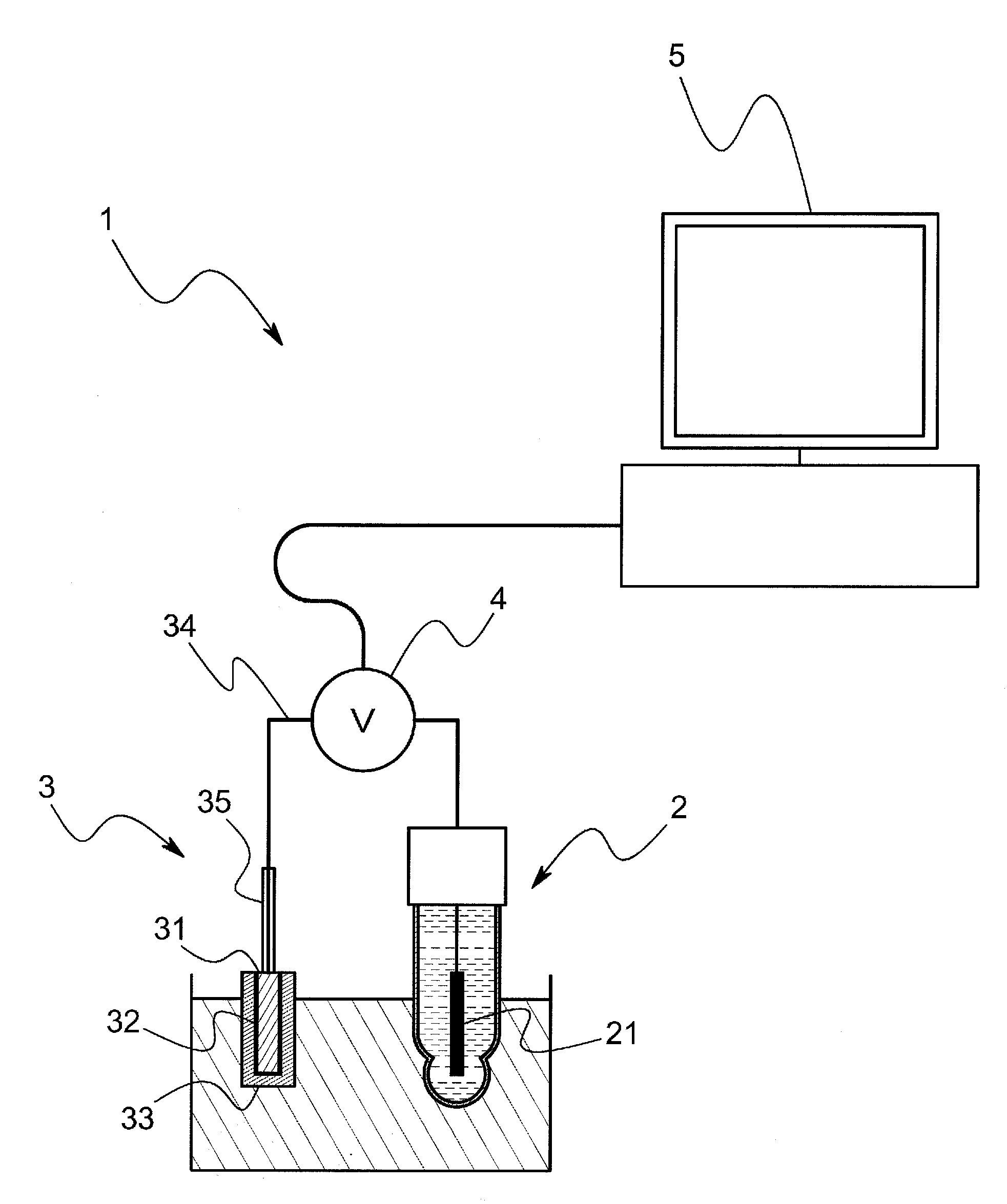
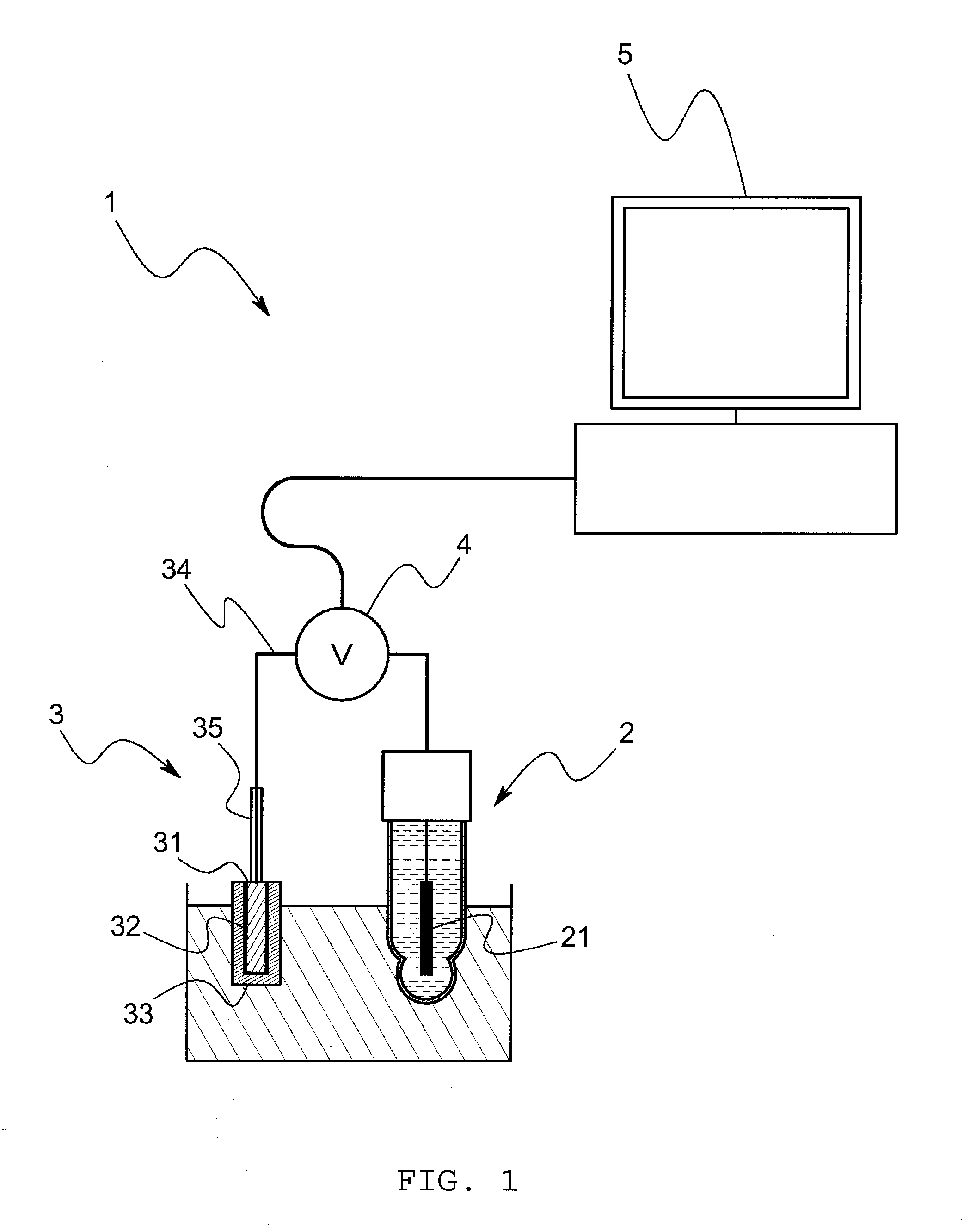
[0072]The model system of this embodiment comprises, as shown in FIG. 3, a voltage measurement cell and an electrometer that measures a voltage E between terminals of the voltage measurement cell. The voltage measurement cell is so arranged that porous glass is sandwiched between a hydrophobic ionic liquid wherein silver chloride is saturated and a sample solution through a hydrophobic ionic liquid, and an Ag / AgCl electrode is inserted into the hydrophobic ionic liquid and the sample solution respectively. The model system comprises a cooling mechanism to keep the voltage measurement cell at a constant temperature (for example, 25° C.) In addition, in this embodiment, the hydrophobic ionic liquid is C8mimC1C1N comprising a combination of a 1-octyl-3-methyl imidazolium ion and a bis(perfluoromethylsulfanilyl)imide i...

embodiment 2

[0077]Next, an embodiment 2 of measurement of the voltage between terminals by a model system using the reference electrode of the present claimed invention will be shown.

[0078]The model system of this embodiment comprises, as shown in FIG. 8, a voltage measurement cell and an electrometer that measures a voltage E between terminals of the voltage measurement cell. The voltage measurement cell is so arranged that a distal end portion of an Ag / AgCl electrode is covered by a gelatinized hydrophobic ionic liquid and the distal end portion is inserted into the sample solution, and an ordinary Ag / AgCl electrode is inserted into the sample solution. In this embodiment, similar to the above-mentioned embodiment, the hydrophobic ionic liquid is C8mimC1C1N, and gelatinized by vinylidene fluoride-hexafluoropropylene copolymer. In addition, AgCl is contained in a saturated state in the hydrophobic ionic liquid.

[0079]In accordance with the model system having the above arrangement, a voltage E ...

other modified embodiment

[0085]The present claimed invention is not limited to the above-mentioned embodiments.

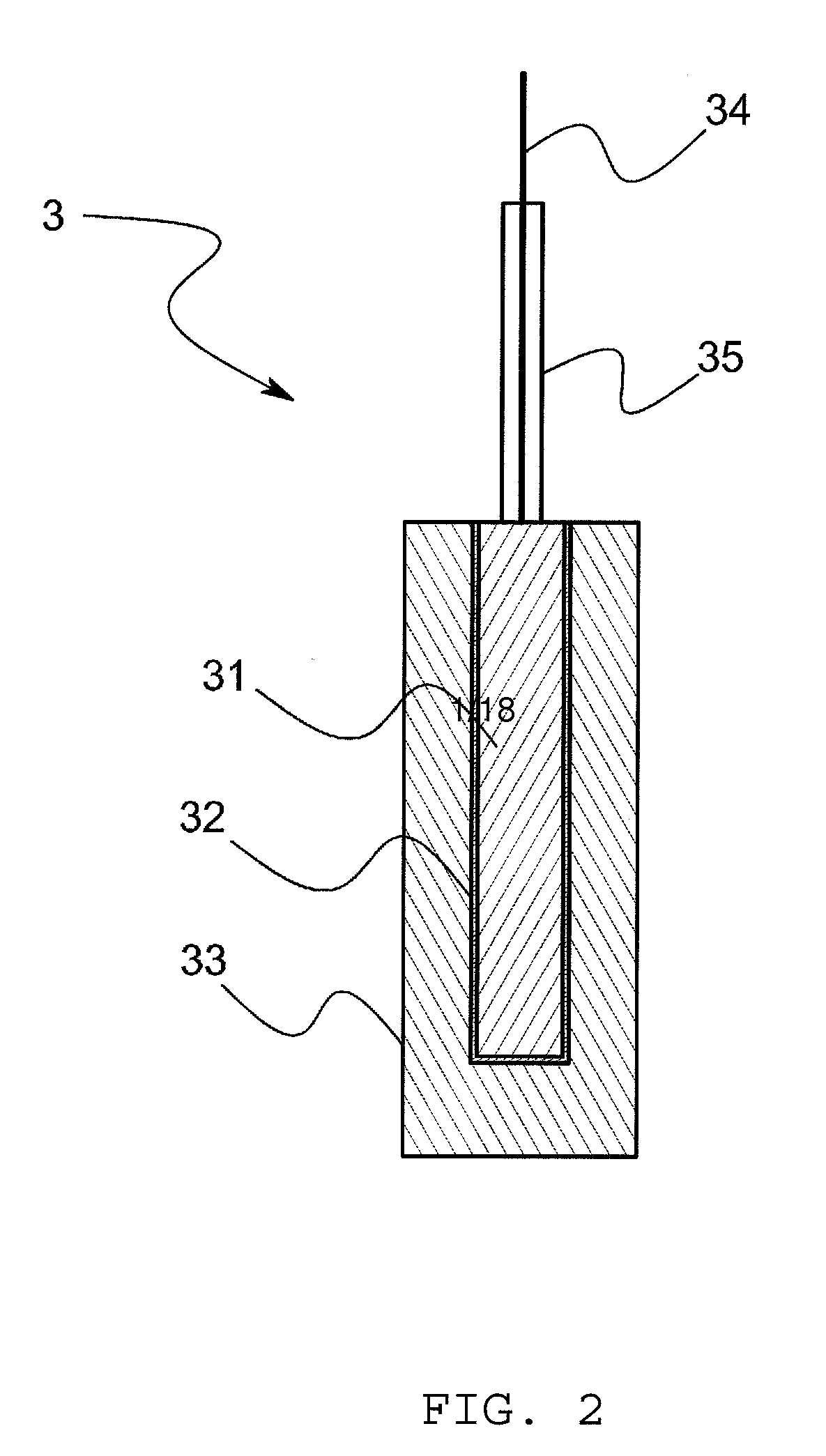
[0086]For example, in the above-mentioned embodiment, it is possible to omit a sling tube if the gelatinized hydrophobic ionic liquid 33 is used, however, the hydrophobic ionic liquid 33 that is not gelatinized may be accommodated in a sling tube 36. In this case, as shown in FIG. 14, the reference electrode 3 comprises a metal body 31, a slightly soluble salt film 32 that covers the metal body 31 and that is made of a slightly soluble salt of the metal body 31, a hydrophobic ionic liquid 33 that is arranged to make contact with the slightly soluble salt film 32, and a sling tube 36 that accommodates the hydrophobic ionic liquid 33 and that has a junction 361 to make the hydrophobic ionic liquid 33 contact with the sample solution. In accordance with this arrangement, since the hydrophobic ionic liquid 33 that is extremely low-volatility at normal temperature is used without using an internal aqueo...


PUM

PropertyMeasurementUnit
temperatureaaaaaaaaaa
solubleaaaaaaaaaa
hydrophobicaaaaaaaaaa

Abstract

This invention provides a reference electrode (3) that can be downsized and stable in voltage. The reference electrode (3) in accordance with this invention is a reference electrode (3) that does not require an internal aqueous solution such as a KCl aqueous solution and comprises a metal body (31), a slightly soluble salt film (32) that comprises a slightly soluble salt of the metal body (31) and that coats the metal body (31) and a hydrophobic ionic liquid (33) that is arranged to make contact with both the slightly soluble salt film (32) and a sample to be measured.

Description

FIELD OF THE ART[0001]This invention relates to a reference electrode that can be a reference for calculation or measurement of an electrode potential and an electrochemical measurement system using the reference electrode.BACKGROUND ART[0002]Presently most extensively used reference electrodes (comparison electrode) such as silver / silver chloride electrodes (Ag / AgCl electrode) or calomel electrodes (Hg / Hg2Cl2) are used to generate a stable potential by immersing an electrode comprising a metal body and a slightly soluble salt film that covers the metal body and that is made of slightly soluble salt to the metal in an aqueous solution comprising an anion constituting the slightly soluble salt such as, for example “chloride salt ion (Cl−), and are referred to herein as reference electrodes based on a second electrode principle. The potential of such a reference electrode is stable, however, since the potential depends on the Cl− concentration in the internal aqueous solution, it is n...

Claims


Application Information

Patent Timeline
Patent Type & Authority Applications(United States)
IPC IPC(8): G01N27/30
CPCG01N27/401
Inventor KAKIUCHI, TAKASHINOMURA, SATOSHIYAMANUKI, MIKITOIWAMOTO, YASUKAZUSHIBATA, MANABU
Owner HORIBA LTD
Why Eureka
Try Eureka