Method of cutting single crystals

a single crystal and cutting technology, applied in the field of single crystal cutting, can solve the problems of complex fracture mode, inability to control crack progress, and inability to produce only such cleavage planes in practice, and achieve the effect of sufficient quality of cleavage planes and high precision

Active Publication Date: 2009-11-19
FREIBERGER COMPOUND MATERIALS
View PDF7 Cites 6 Cited by
  • Summary
  • Abstract
  • Description
  • Claims
  • Application Information

AI Technical Summary

Benefits of technology

[0011]In theory the production of completely planar cleavage surfaces could be achieved where a planar tensile stress field perpendicular to a desired cleavage plane is generated. In this case the stress fields and the cleavage plane would be coordinated with each other to such an extent that these do not compete with each other. However, these conditions can not be kept in practice. For example, it would have to be required in the case of cleaving laser components, that the wafer must be oriented with high precision with respect to the cleavage device, in order to achieve a sufficient quality of the cleavage plane at least over the length of the laser component. Even with the smallest deviations of the wafer orientation with respect to the generated tensional fields, steps formed on the cleavage plane will become inevitable.
[0012]It is an object of the invention, to provide a method of dividing single crystals, which avoids the above mentioned disadvantages and which secures exact cleavage planes over a full distance up to the complete separation of the desired parts.
[0013]The object is solved by a method according to claim 1, or by a single crystal according to claims 13 or 14. Embodiments and aspects of the invention are set forth in the dependent claims.
[0014]According to the invention, cleavage planes having accuracies in the range of ≦|0.02°|, |0.01°|, |0.005°| or even less than |0.001°|—as measured over the

Problems solved by technology

However, a disadvantage of the mechanical cleaving device arises in that the crack progress can not be controlled, and in that due to the initialization of the breakage by means of a seed break at the wafer edge a complex fracture mode is realized.
As a consequence, employing the above-described methods one is restricted in practice to

Method used


Image

  • Method of cutting single crystals
  • Method of cutting single crystals
  • Method of cutting single crystals

Examples


Embodiment Construction

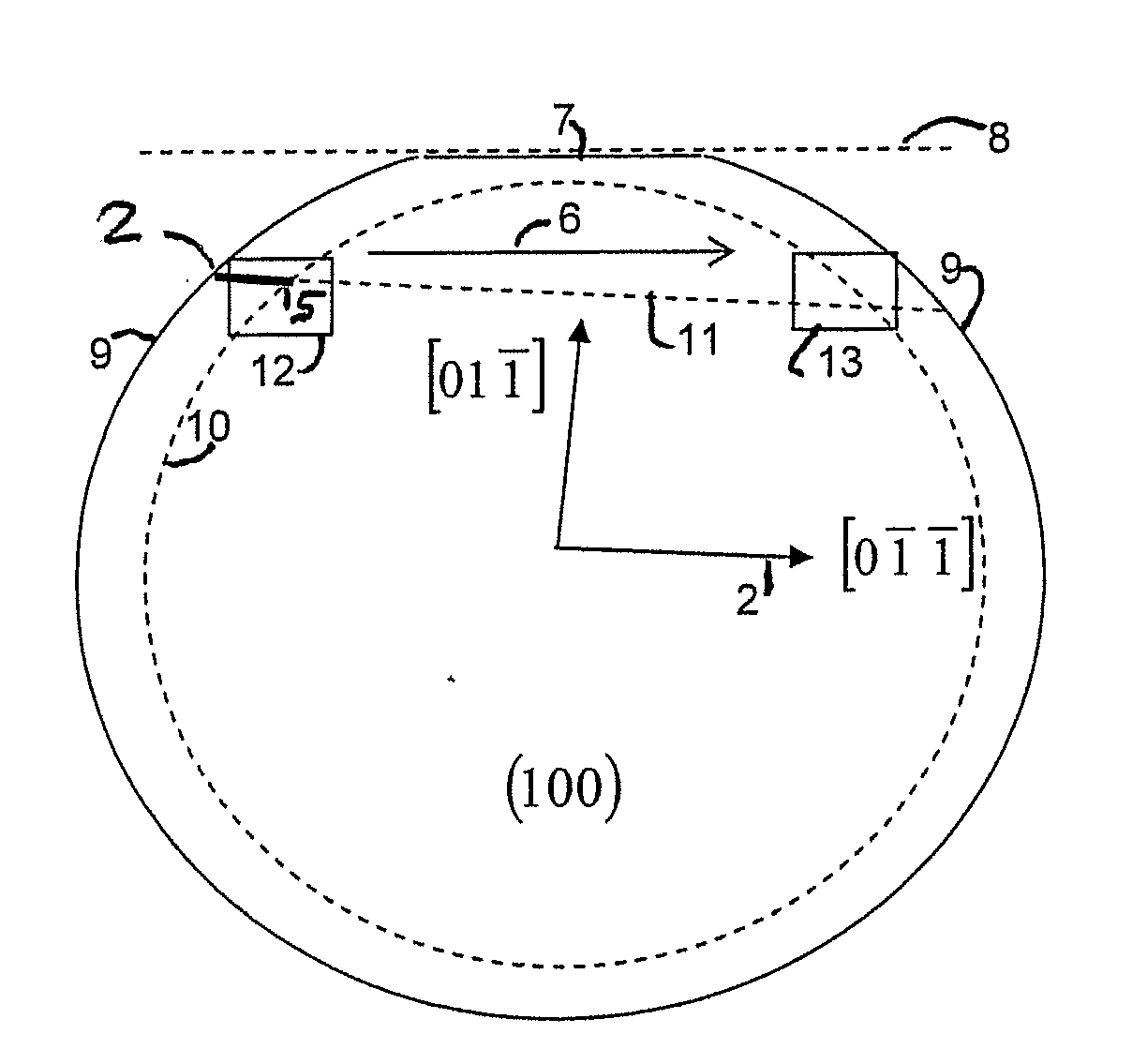
[0035]In the following the invention is described by means of an embodiment of a cleaving process of a GaAs-Wafer by means of thermally induced stress fields. At first, the wafer is provided to the cleavage device. The adjustment of the wafer with respect to the cleavage device is performed by virtue of a previously formed marking, e.g., a short flat, which by means of example is grinded and oriented by means of X-ray diffractometry. Thereby an accuracy of the flat orientation with respect to the {110}-cleavage plane of 0.1° can be achieved in practice. Similarly, other markings or short flats perpendicular or in a predetermined relation to the cleavage planes may be considered as pre-adjustment means. The pre-adjustment with respect to the movement direction may be carried out with the help of stops or employing optical methods.

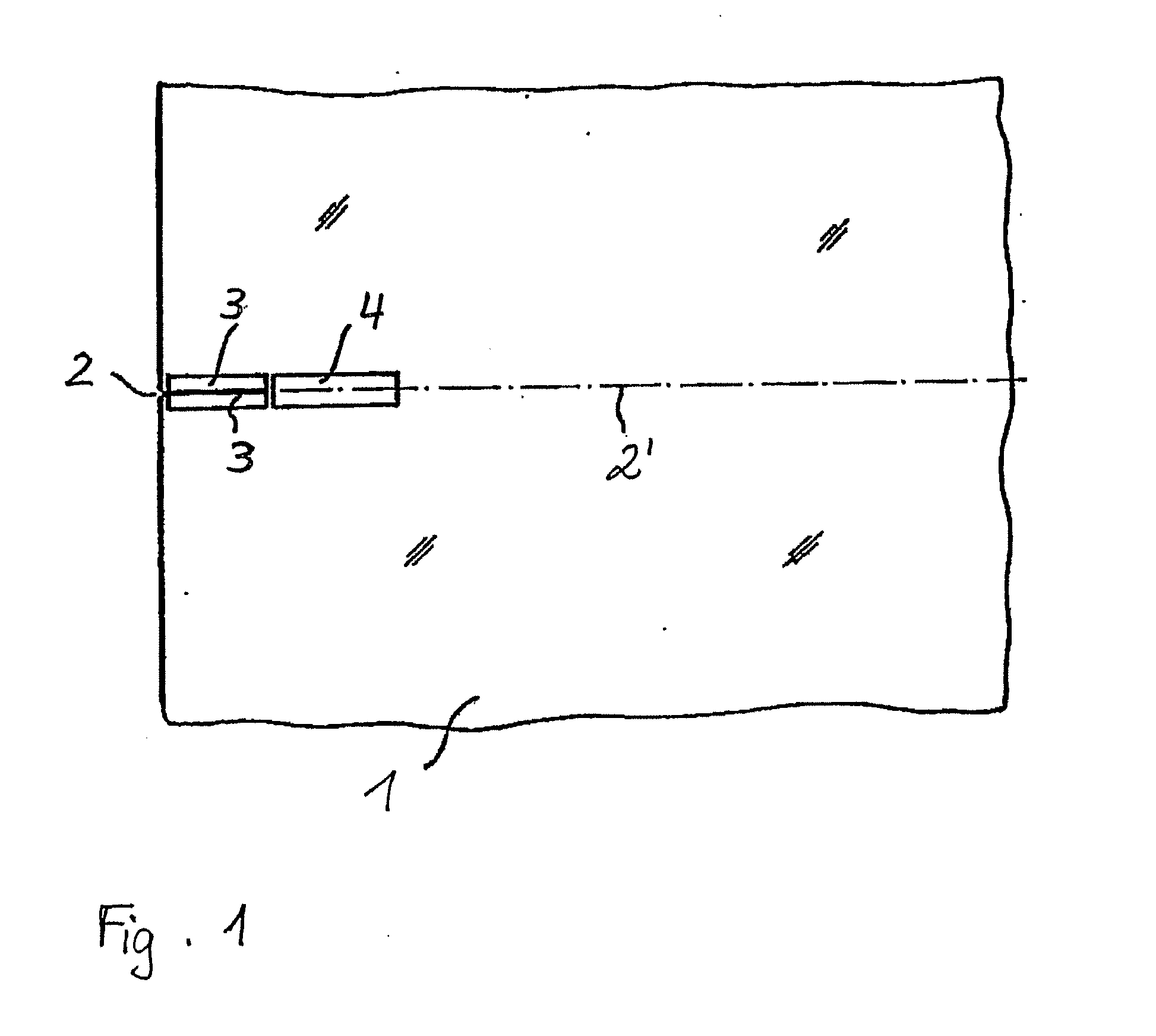
[0036]As becomes schematically evident from FIG. 1, an initial crack 2 is formed in a {110}-cleavage plane of the GaAs-wafer 1. Ideally, the initial crack 2...


PUM

PropertyMeasurementUnit
Lengthaaaaaaaaaa
Structureaaaaaaaaaa
Surface areaaaaaaaaaaa

Abstract

A method of dividing single crystals, particularly of plates of parts thereof, is proposed, which can comprise: pre-adjusting the crystallographic cleavage plane (2′) relative to the cleavage device, setting a tensional intensity (K) by means of tensional fields (3′, 4′), determining an energy release rate G(α) in dependence from a possible deflection angle (α) from the cleavage plane (2′) upon crack propagation, controlling the tensional fields (3′, 4′) such that the crack further propagates in the single crystal, wherein G(0)≧2γe(0) and simultaneously at least one of the following conditions is satisfied:
Gαα=02βehif2Gα20or(2.1)Gα2βehα:α1<α<α2,(2.2)

Description

CROSS REFERENCE AND PRIORITY[0001]This application claims the benefit of U.S. Provisional Application 60 / 996,396, filed Nov. 15, 2007, entitled “Verfahren zum Trennen von Einkristallen”, which is hereby incorporated by reference in its entirety. This application further claims the benefit of German Application No. 10 2007 056 115.8, filed Nov. 15, 2007, entitled “Verfahren zum Trennen von Einkristallen”, which is hereby incorporated by reference in its entirety.FIELD OF THE INVENTION[0002]The invention relates to a method of separating single crystals, e.g., single crystalline plates or wafers or parts thereof. In particular, the application relates to a method of dividing single crystals including a crack propagation that is self-adjusting.TECHNICAL BACKGROUND[0003]Single crystalline wafers comprising semiconducting materials are used as substrates for the manufacturing of micro-electronic components such as field effect or hetero-bipolar transistors, and of opto-electronic compone...

Claims


Application Information

Patent Timeline
IPC IPC(8): H01L29/24C30B29/42C30B29/44C30B29/06C30B29/40C30B29/00C30B29/36C30B29/20C30B29/38B32B3/10B32B9/00B32B15/20H01L29/20H01L29/26H01L29/161H01L29/04B28D5/00B26F3/00
CPCB28D5/00B28D5/0064Y10T428/24802Y10S117/915H01L21/78Y10T225/12Y10T428/31678
Inventor HAMMER, RALFJURISCH, MANFRED
Owner FREIBERGER COMPOUND MATERIALS
Why Eureka
Try Eureka