Rotating flexible wing power system

a flexible wing and power system technology, applied in the field of aeropower and hydropower, can solve the problems of difficult access to the system and generator, large capital costs for construction, operation and maintenance, and inability to easily position the blades for maximum angle of attack, so as to ensure the safety of generating power and optimize the effect of mass distribution

Inactive Publication Date: 2009-11-19
LABRECQUE DAVID R
View PDF9 Cites 15 Cited by
  • Summary
  • Abstract
  • Description
  • Claims
  • Application Information

AI Technical Summary

Benefits of technology

[0010]The present invention discloses a low-cost system for safely generating power from the flow of fluids by the use of a single curved flexible wing supported at each of its two ends by corresponding support structures. The wing employs a pair of rotation mechanisms interposed between the ends of the wing and the support structures, with the rotation mechanisms suitably adapted to allow the wing to rotate or swing freely around a central axis. Introduction of a flowing fluid over the wing results in lift forces which rotate the wing in a manner similar to a rigid Darrieus wind turbine. The wing continues through its rotation and is returned to the upwind position by angular momentum. Unlike a Darrieus wind turbine, however, the present invention utilizes a single flexible wing rather than a plurality of rigid wings, and the wing has an optimized mass distribution. The lift forces on the wing change the shape and position of the wing relative to the center of rotation, making the radius of rotation longer on the downwind side (when the wing is bowed out by the force of the wind on the concave inner surface of the wing) and shorter on the upwind side (when the wing is flattened by the force of the wind on the convex outer surface of the wing). The changes to the radius length correspond to a continuous change in the distance between the ends of the wing, with the distance between the ends shorter on the downwind side and longer on the upwind side, resulting in the wing creating longitudinal oscillations of its ends having a relatively large amount of force. The energy from these longitudinal oscillations is captured and may be used to drive a generator or pumping device. A fluid other than air may be used, such as a water current, with the same effect.

Problems solved by technology

While effective, this design requires an additional mechanism to point it into the wind and it lacks the ability to easily position the blades for maximum angle of attack when the wind shifts.
Moreover, traditional windmills are typically massive structures requiring considerable capital costs for construction, operation, and maintenance.
Where windmills are combined with generators to produce electricity, the generators are typically located on the support structure, making access to the system and generator difficult.
While traditional windmills have been improved upon by the use of rotatable blades for actively changing the blade angle under various wind conditions, such changes have added to the complexity and cost of the design, without addressing the inherent drawbacks of the design.
However, an inherent flaw with the Darrieus design is the difficulty of building lightweight rigid blades that can handle heavy wind loads.
Some prototypes have failed catastrophically in high winds with blade parts flying dangerously outwards at high speeds.
Although the device generates high torque, the high stresses in the device require a large structural mass to unit area ratio.
This and its utilization of inefficient wind drag forces rather than lift forces make it less efficient and less viable than traditional windmills.
The fundamental feature of these devices is that the airfoil's angle to the wind is continuously increased and decreased resulting in an oscillating movement.
These devices have the advantage of being easily oriented to the direction of wind flow for maximum energy capture during energy capture, as well as being able to reach higher elevations where the wind is stronger without the need for expensive load-bearing towers, but they have the disadvantage of requiring complicated systems for controlling and resetting the airfoils and are susceptible to complete operational shutdown when the wind velocity decreases below a minimum level.
Once the tethers have reached maximum extension they need to be retracted, which results in the airfoils being drawn against the air flow with a resulting loss of efficiency.
Means are employed to manipulate the orientation of the airfoils relative to the air flow to better allow withdrawal against the air flow, but substantial energy is nevertheless wasted during airfoil retraction.
These disadvantages make these designs more difficult and expensive to operate than traditional wind systems.

Method used


Image

  • Rotating flexible wing power system
  • Rotating flexible wing power system
  • Rotating flexible wing power system

Examples


Embodiment Construction

Overview

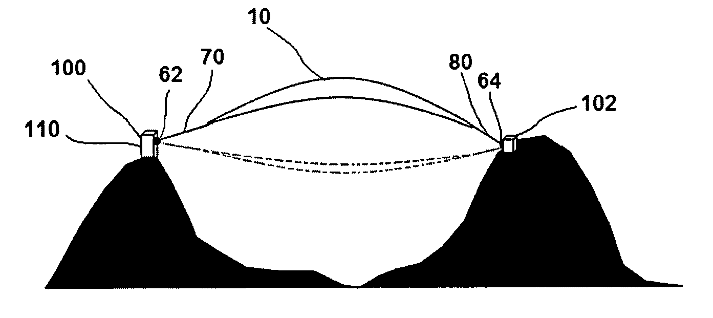
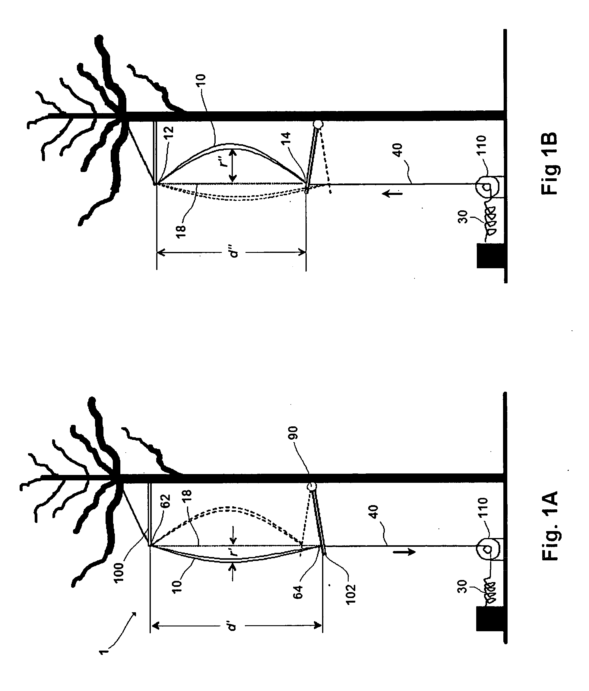
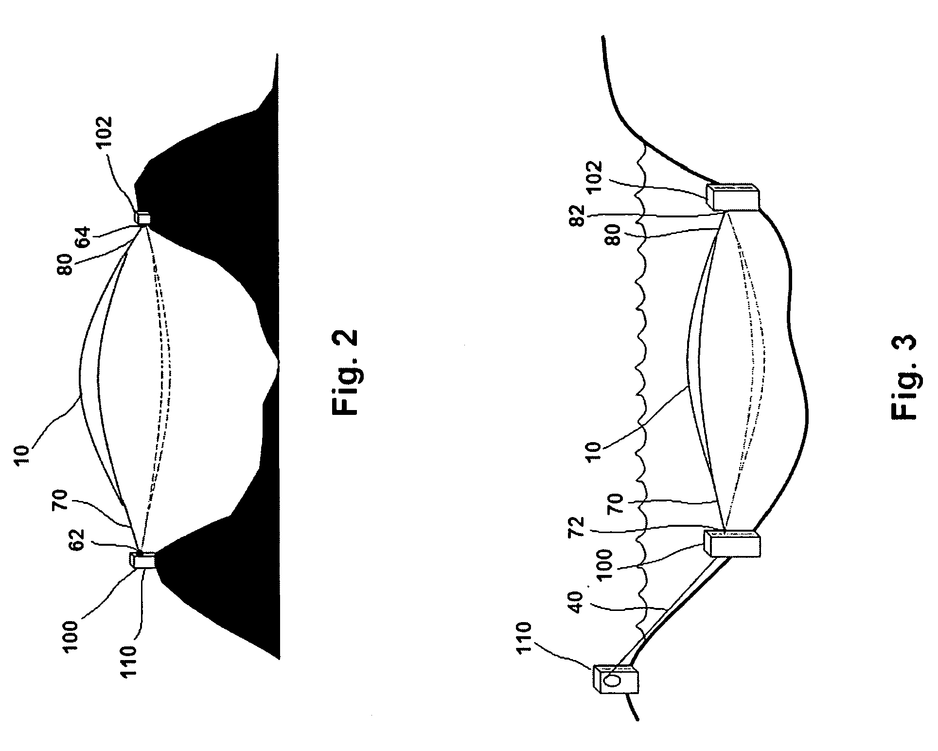
[0042]Turning now descriptively to the drawings, in which similar reference characters denote similar elements throughout the several views, the figures illustrate a single long flexible wing 10 supported at its ends 12,14 so that it can rotate or swing around a central axis 18. See FIGS. 1A and 1B. Rotation mechanisms 62,64 are located at each end 12,14 of the wing 10 allowing the wing 10 to rotate freely. One or both ends 12,14 of the wing 10 may be connected to tethers 70,80 interposed between the main portion of the wing 10 and the rotation mechanisms 62,64. Energy is extracted from the longitudinal oscillations as the wing 10 rotates in a flowing fluid like air, either directly or through a force transfer member 40 to a generator 110 or pumping device positioned at a convenient location. The device is thus seen to efficiently convert rotational energy to linear energy.

Long Flexible Wing

[0043]The long flexible wing 10 is designed to withstand large tensile, oscillating, ...


PUM


Abstract

A Rotating Flexible Wing Power System for extracting low-cost electricity and mechanical energy from moving fluids including wind and water currents. The Rotating Flexible Wing Power System generally includes a single long curved flexible wing supported at its ends so that it can rotate or swing around a longitudinal axis that intersects the endpoints of the wing. Rotation mechanisms are located at each end of the wing allowing the wing to rotate freely about its longitudinal axis. Lift forces on the wing resulting from the moving fluid cause the wing to start and continue rotating. These lift forces also create oscillating longitudinal forces in the flexible wing which move the ends of the flexible wing towards and away from each other. This movement may be harnessed to drive a generator or pumping device connected to the flexible wing. One or both ends of the wing can be connected to tethers so that the overall length of the flexible wing is increased. A force transfer member can be used to extend the reach of the system so that energy can be extracted from the flexible wing to a generator or pumping device positioned at a convenient distant location.

Description

CROSS REFERENCE TO RELATED APPLICATION[0001]This application claims priority to a provisional application, U.S. Ser. No. 61 / 053,569, filed May 15, 2008, entitled Rotating Flexible Wing Power System, by Labrecque, David, which is hereby incorporated by reference.BACKGROUND OF THE INVENTION[0002]1. Technical Field[0003]The present invention relates generally to aero-power and hydropower and more specifically it relates to a Rotating Flexible Wing Power system for extracting low-cost electricity and mechanical energy from moving fluids including wind and water currents.[0004]2. Description of Prior Art[0005]Traditional windmills are the most common examples of devices used to capture energy from moving fluids, namely wind. The multiple blades of the windmill rotate about a horizontal axis oriented preferably in parallel with the air flow. The rigid cantilevered blades must be properly angled at each point along their length to optimize rotation. While effective, this design requires an...

Claims


Application Information

Patent Timeline
Patent Type & Authority Applications(United States)
IPC IPC(8): F03D3/00F03D9/00
CPCF03D3/00F05B2240/212F05B2240/911Y02E10/74Y02B10/70Y02E10/728Y02B10/30Y02P80/10
Inventor LABRECQUE, DAVID R.
Owner LABRECQUE DAVID R
Why Eureka
Try Eureka