
Method and system for cutting knee joint using robot

a robot and knee joint technology, applied in the field of surgery using robots, can solve the problems of difficult to precisely insert an artificial joint, excessive bone damage, and high risk of bone damage in the milling of bone or surrounding tissue,

Inactive Publication Date: 2009-11-19
TRABISH MASEI MARTY +1
View PDF7 Cites 63 Cited by
  • Summary
  • Abstract
  • Description
  • Claims
  • Application Information

AI Technical Summary

Benefits of technology

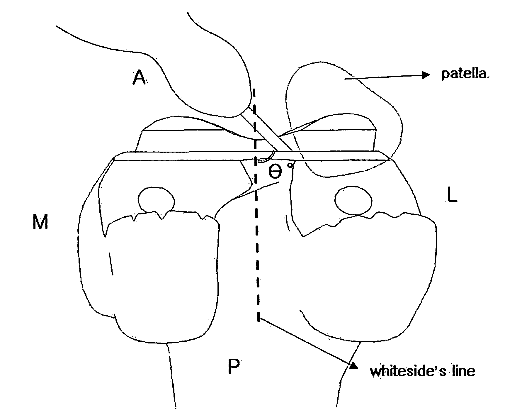
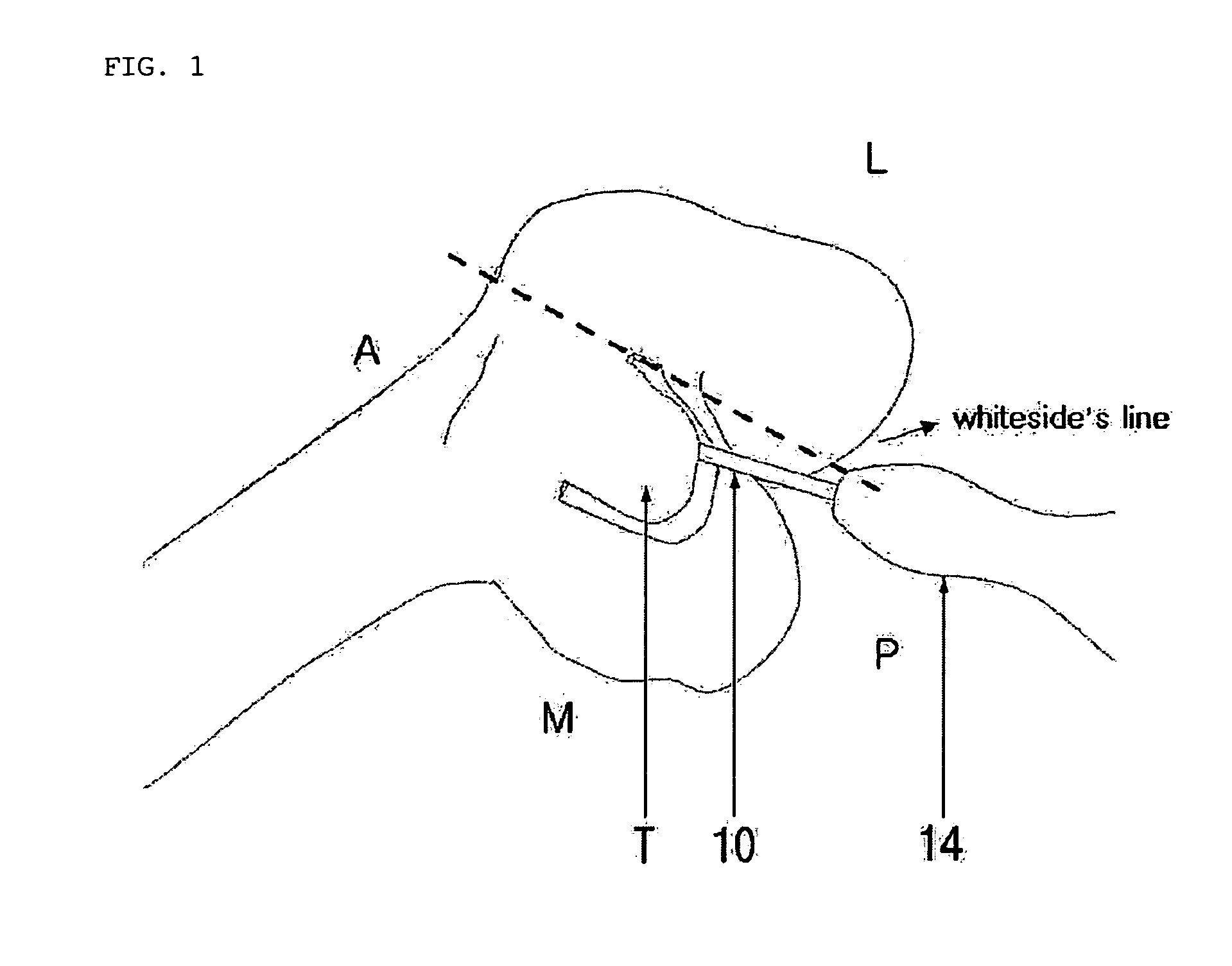
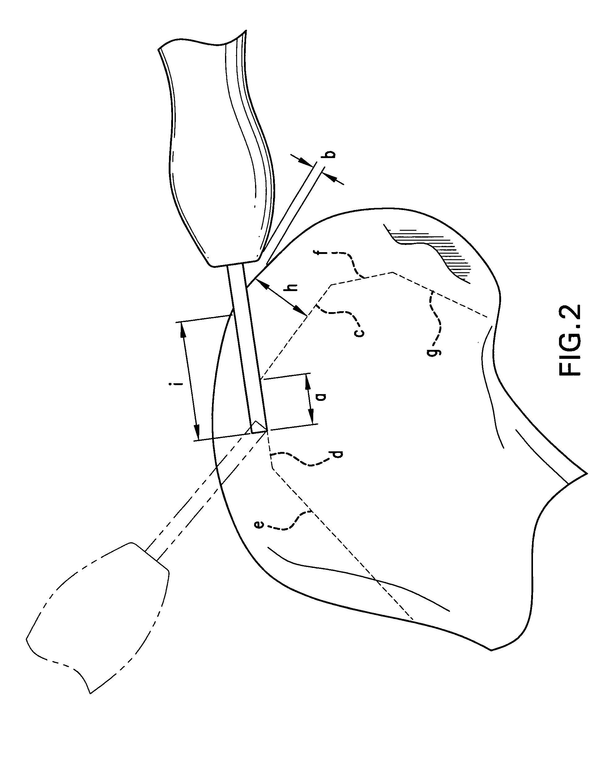
"The present invention provides a method and system for cutting the knee joint using a robot in a minimal invasive replacement surgery. The method involves using a cantilevered cutter with a small diameter that is introduced into the knee joint from inside and outside of the bones to realize a tunnel cutting technique in which tunnels are defined in the bone and remnant bone is cleared. The cutter is moved while being kept parallel to the Whiteside's line when cutting the upper bone and slanted to a prescribed angle with respect to the line when cutting the lower bone to avoid impingement between the cutter and surrounding tissue. The system includes a position-changeable arm, a motor, a sleeve, and a cutter, with the cutter having a shaft with a round bar shape and a remaining axial portion serving as a cantilever extending out of the sleeve. The cutter is made of a material with a hardness in the range of HRC80˜120 and has chatter blockers to prevent chattering during cutting. The technical effects of the invention include minimizing damage to important tissue, reducing the size of incisions, and achieving efficient and quick surgery."

Problems solved by technology

In arthroplasty which is currently and directly conducted by a surgeon, since bone milling is not precise, it is difficult to precisely insert an artificial joint.
Also, due to the imprecise insertion of the artificial joint, various complications may arise, and because the lifetime of the artificial joint is not so long, inconvenience is caused in that it is necessary to conduct surgery again some time in the future.
However, in the case that master surgeon directly conduct surgery, since it is difficult to handle precisely the surgery instruments and mill precisely the bone, an excessive amount of the bone is likely to be damaged during the milling of the bone or surrounding tissue is likely to be damaged.
However, although the conventional method and the system contribute to some extent to the improvement in the precision of the surgery, they suffer from defects as described below.
Also, due to the rotation of the head 110 having the large size, it is difficult to properly protect the important tissue such as the periosteum attached to the bone, and serious damage to the bone can be caused.
Moreover, because a substantial amount of foreign substance such as bone particles are produced during milling, a surgery condition is deteriorated, and as the bone particles are introduced into the surrounding tissue, an inflammation may be caused after conducting the surgery, which can lead to a sequela of the surgery.
Further, since the conventional method and system adopt the top down milling scheme in which the bone is gradually milled out level by level, a lengthy period of milling time is required and a surgery time is extended as well.
In addition, while the conventional level to level milling method has a characteristic in terms of precision, the patient and the master surgeon who has performed the surgery cannot be satisfied only with the precision.
Nevertheless, since the surgery is performed in a narrow space, the tissue is excessively retracted and therefore is likely to be damaged.
Also, due to the incision of the skin to the lesser degree, the field of view becomes narrow, and it is difficult to insert precisely the implant.

Method used


Image

  • Method and system for cutting knee joint using robot
  • Method and system for cutting knee joint using robot
  • Method and system for cutting knee joint using robot

Examples


Embodiment Construction

[0044]The present invention includes all devices for the positioning, the moving and the force feedback mechanisms of a cutting system mounted to the distal end of a robot to implement minimal / less invasive surgery. Also, the present invention includes the devices which are arranged on the distal end of the robot having multi-degree of freedom and perform a cutting operation, the devices involving a power generation device, a power transmission device, a sensor for monitoring cutting force applied to an end effecter, and cutters having various diameters necessary for cutting bone.

[0045]Also, the present invention includes a cutting system which involves a short cantilevered rotary cutter for minimal incision, and a tunnel type cutting method.

[0046]Moreover, the present invention includes chatter blockers (chatter prevention technology) which are formed on the distal end of the head of the cantilevered cutter, the retention of a helix angle of 10˜20° on the circumferential outer surf...


PUM


Abstract

A method and a system for cutting the knee joint using a robot. A cantilevered cutter is introduced into the knee joint from inside and outside of upper and lower bones of the knee joint to realize a tunnel cutting technique in which cutting is conducted such that tunnels are defined in bone and remnant bone is cleared. The cutter includes a shaft in which a substantial axial portion is fitted into a sleeve and a remaining axial portion serves as a cantilever extending out of the sleeve, and a head which is formed at a distal end of the shaft. A length of the cantilever and a diameter of the head are determined to have minimum sizes as long as the head can be introduced into bone in such a way as to define a tunnel and can be moved in the bone while cutting the bone.

Description

BACKGROUND OF THE INVENTION[0001]1. Field of the Invention[0002]The present invention relates to surgery using a robot, and more particularly, to a method and a system for cutting the knee joint using a robot, wherein a surface, on which an artificial joint is to be coupled to the knee joint, can be formed with maximum safety and high precision in implementing total knee replacement arthroplasty while minimizing the incision of the skin by the robot without causing damage to the tissue around the patella.[0003]2. Description of the Related Art[0004]These days, as old age population increases, arthritis and osteoporotic hip fracture tend to increase.[0005]In this regard, by directly implementing knee replacement arthroplasty rather than using an indirect therapy such as parmacotherapy, physical therapy and intra-articular injection therapy, which is mainly used in the past, early mobilization is enabled without pain. Also, with the development of joint mechanics, the lifetime of an a...

Claims


Application Information

Patent Timeline
Patent Type & Authority Applications(United States)
IPC IPC(8): A61B19/00A61B17/00
CPCA61B17/1615A61B17/1633A61B2017/564A61B19/2203A61B17/1675A61B34/30A61B17/16A61B17/32
Inventor LEE, CHUN TEKYOON, SUNG HWANKWON, OH MYOUNGPARK, JOON SIKLEE, HANG JAEKANG, MI ROTRABISH, MASEI MARTYKARAN, JAI
Owner TRABISH MASEI MARTY
Learn More