Precast composite structural floor system

a composite floor and floor technology, applied in the direction of bridges, girders, bridge structural details, etc., can solve the problems of requiring more material, requiring more precast members, and requiring more difficult connections between precast members and the rest of the building structure, so as to reduce the overall weight of the building, reduce the amount of floor material, and the effect of tighter and more efficien

Active Publication Date: 2009-11-26
VELOCITY I P
View PDF48 Cites 35 Cited by
  • Summary
  • Abstract
  • Description
  • Claims
  • Application Information

AI Technical Summary

Benefits of technology

[0008]The present invention is a precast composite floor system which is made up of composite floor panels and composite girders. The floor system is able to be fabricated in a factory, shipped to a job site, and erected in a manner that is quicker and more efficient than existing systems. The present invention provides precast panels which are lighter than existing panels. Reducing the amount of material in the floor of a building reduces the overall weight of the building, which in turn allows for smaller columns, foundations, and lateral systems.

Problems solved by technology

Conventional precast structures, however, suffer from several disadvantages such as being heavy, requiring more material, and requiring more difficult connections between precast members and to the rest of the building structure.
These precast floor panels are heavy.
Heavy floor panels require heavier columns and beams to support the floor panels and so on, increasing the weight of nearly every part of the building structure.
Heavier structural elements use more materials and are thus more expensive, require increased lateral and vertical support, and may limit the height of the building for a particular soil load bearing capacity.
Another drawback of the conventional precast floor systems is that mechanical equipment and ducts must be suspended beneath the beams, increasing the vertical space required for a floor.

Method used


Image

  • Precast composite structural floor system
  • Precast composite structural floor system
  • Precast composite structural floor system

Examples


Embodiment Construction

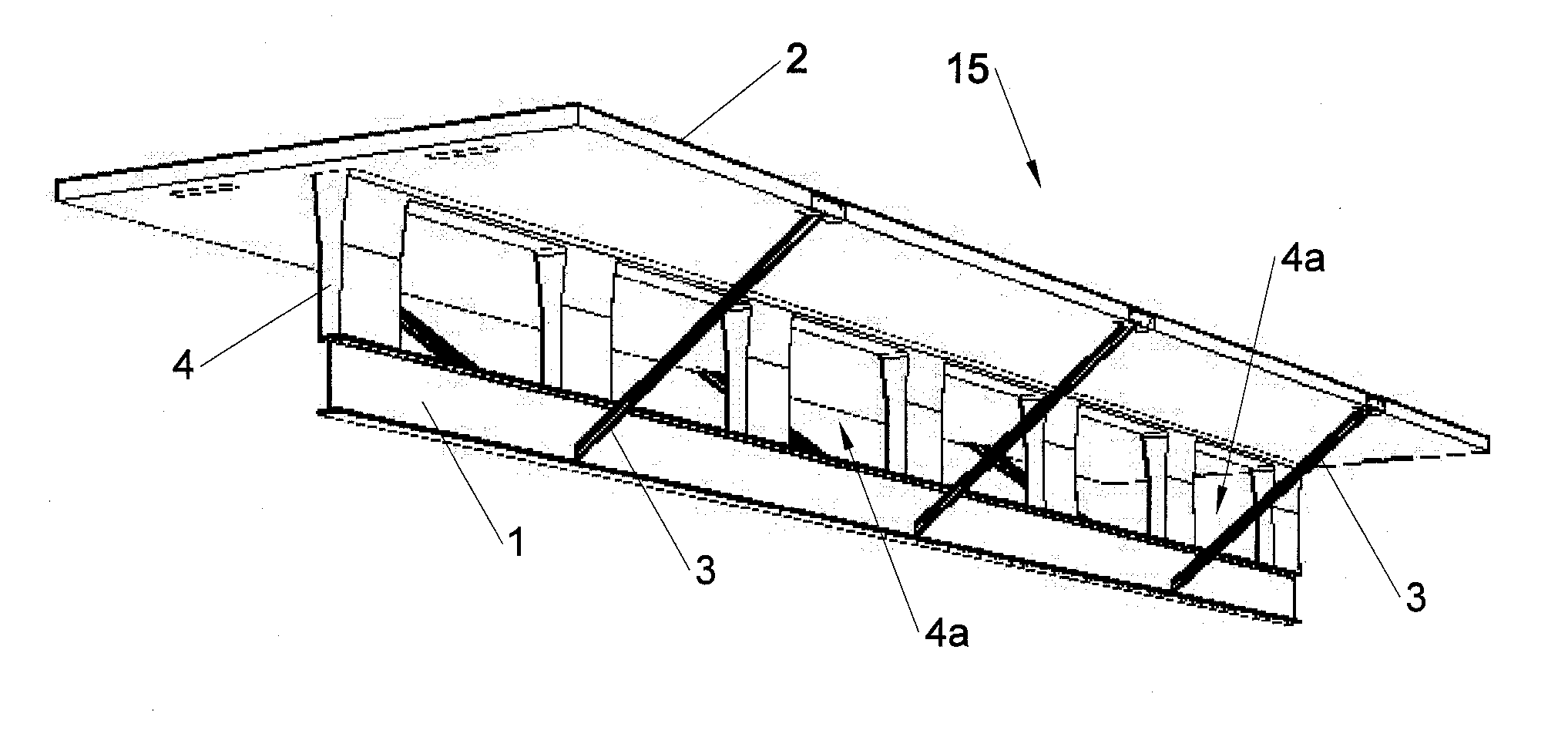
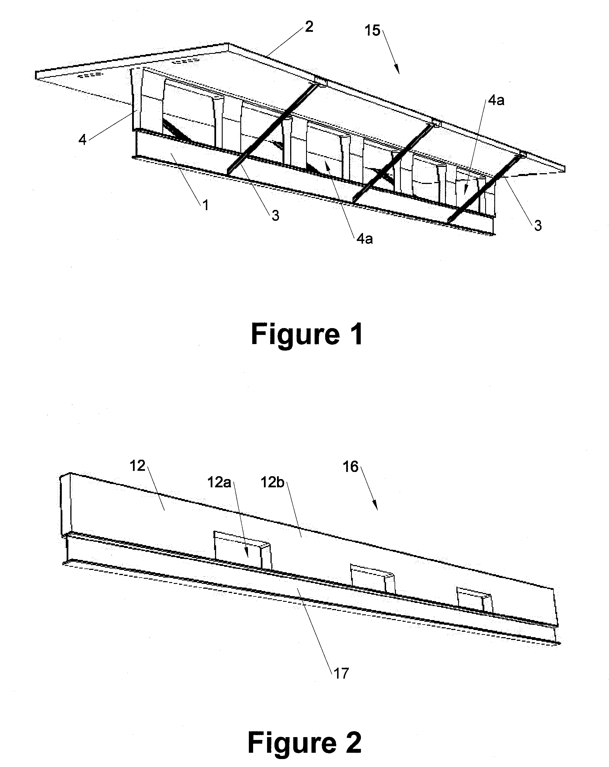
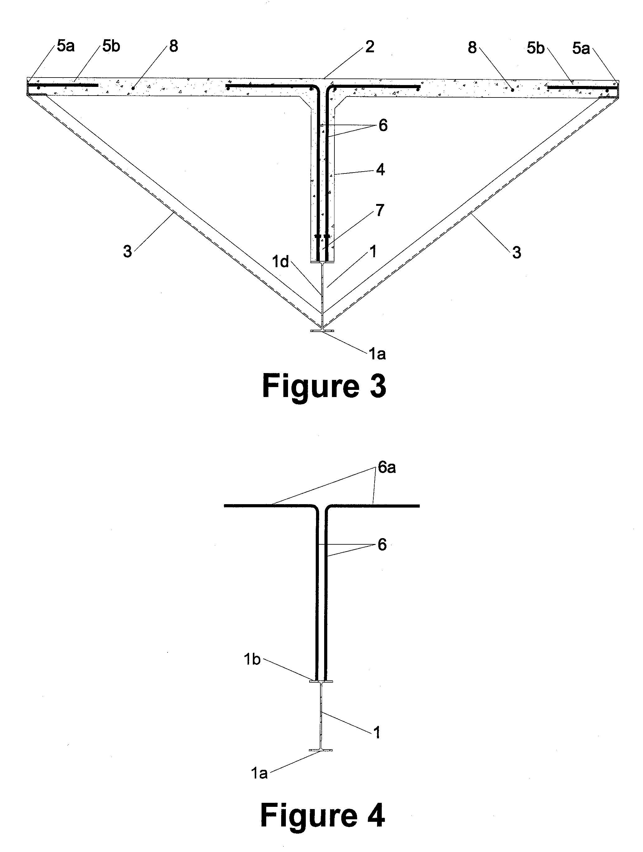
[0040]The invention and accompanying drawings will now be discussed in reference to the numerals provided therein so as to enable one skilled in the art to practice the present invention. The drawings and descriptions are exemplary of various aspects of the invention and are not intended to narrow the scope of the appended claims.

[0041]The present system has several advantages over conventional concrete double tee systems. The biggest advantage is the reduced weight. A concrete double tee system with similar spans and loading conditions would weigh approximately 100% more per square foot than the present invention. Other structural members such as concrete girders and concrete columns that are used with double tee systems are also much heavier than columns used with the present invention. Increased weight of the double tee floor system necessitates larger footings and foundation walls. This is restrictive for taller structures and for construction in areas with poor soil bearing cap...


PUM


Abstract

A precast composite flooring system utilizes girders and floor panels having steel lower structures placed in tension and concrete upper structures places in compression. Openings through a stem wall allow ducts, pipes, and conduits to be run therethrough. The system provides reduced weight over conventional precast or pour in place systems, allowing further reduction in the weight and size of other building components. The floor deck does not use tensioning strands, allowing openings to be formed at nearly any stage of construction and with reduced concern over cutting steel reinforcement. The floor panels and girders bolt together and bolt to a steel column frame, allowing for more efficient assembly.

Description

PRIORITY[0001]The present application claims the benefit of U.S. Provisional Application Ser. No. 61 / 053,147, filed May 14, 2008, which is herein incorporated by reference in its entirety.THE FIELD OF THE INVENTION[0002]The present invention relates to precast composite floor systems. More specifically, the present invention relates to a precast composite floor which provides decreased weight, is able to bolt directly into a steel frame structure, and which allows for forming holes through the floor slab without concern for tensioning strands as well as the passage of mechanical equipment through the vertical stem wall of the floor section.BACKGROUND[0003]Precast concrete construction is often used for commercial and industrial buildings, as well as some larger residential buildings such as apartment complexes. Precast construction has several advantages, such as more rapid erection of a building, good quality control, and allowing a majority of the building structural members to be...

Claims


Application Information

Patent Timeline
Patent Type & Authority Applications(United States)
IPC IPC(8): E04C2/30E04C3/08E04C5/12
CPCE04B5/23E04C3/294E04C3/291E04B5/43
Inventor PLATT, DAVID H.CHARCHENKO, JOHN E.HODGSON, DARYL G.PLATT, RUSSELL J.
Owner VELOCITY I P
Why Eureka
Try Eureka