Knock detection device for a cobustion engine and a method for a combustion knock detection

Inactive Publication Date: 2009-11-26
ROBERT BOSCH GMBH
View PDF17 Cites 10 Cited by
  • Summary
  • Abstract
  • Description
  • Claims
  • Application Information

AI Technical Summary

Benefits of technology

[0010]The gain of the amplifier is adapted based on analysis of a set of samples from the knock sensor such that the amplification o

Problems solved by technology

As the knock sensor amplitude varies over a wide range, the amplification of the signal with a fixed gain will result in loss of resolution under some conditions.
Using a single sample crossing the set threshold to adapt the gain may be faster, but there may be a risk that the single sample may

Method used


Image

  • Knock detection device for a cobustion engine and a method for a combustion knock detection
  • Knock detection device for a cobustion engine and a method for a combustion knock detection

Examples


Example

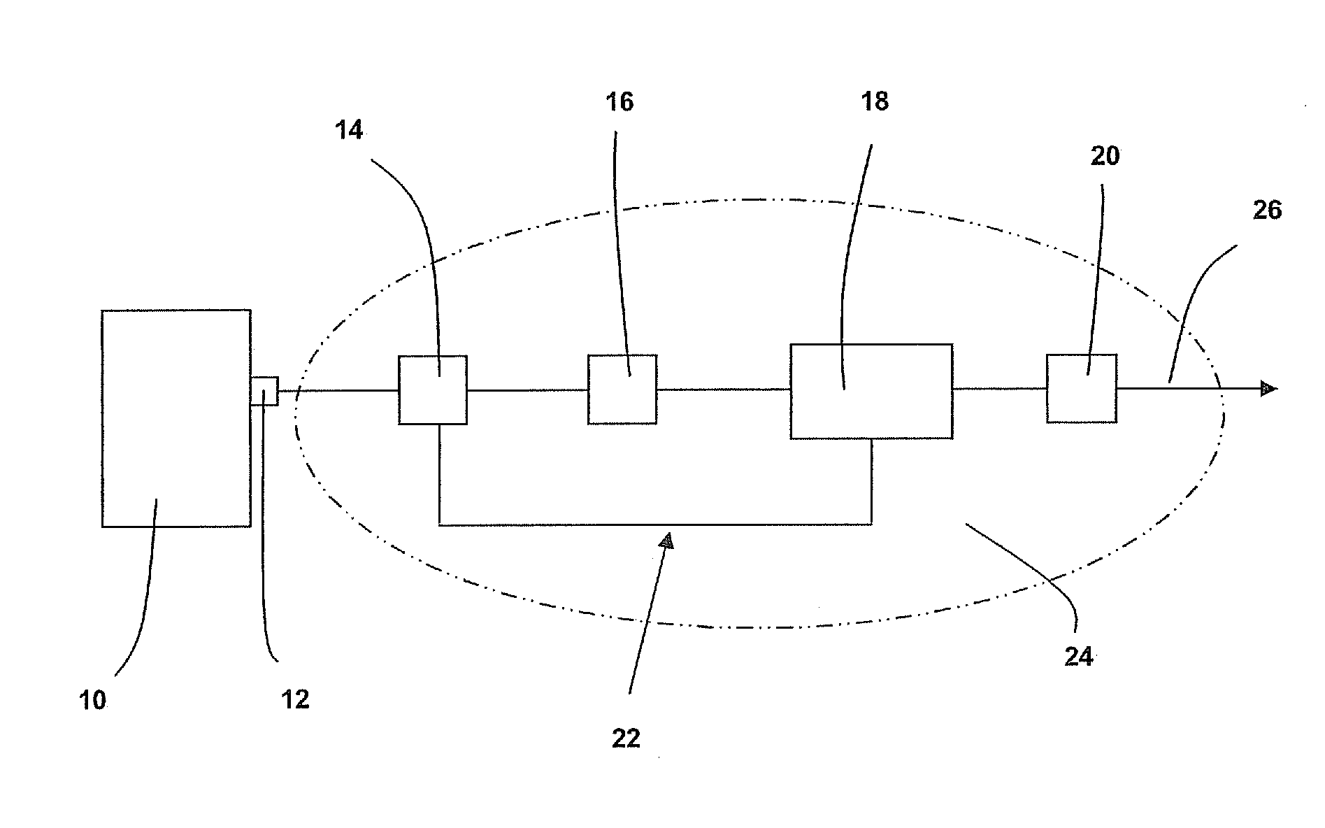
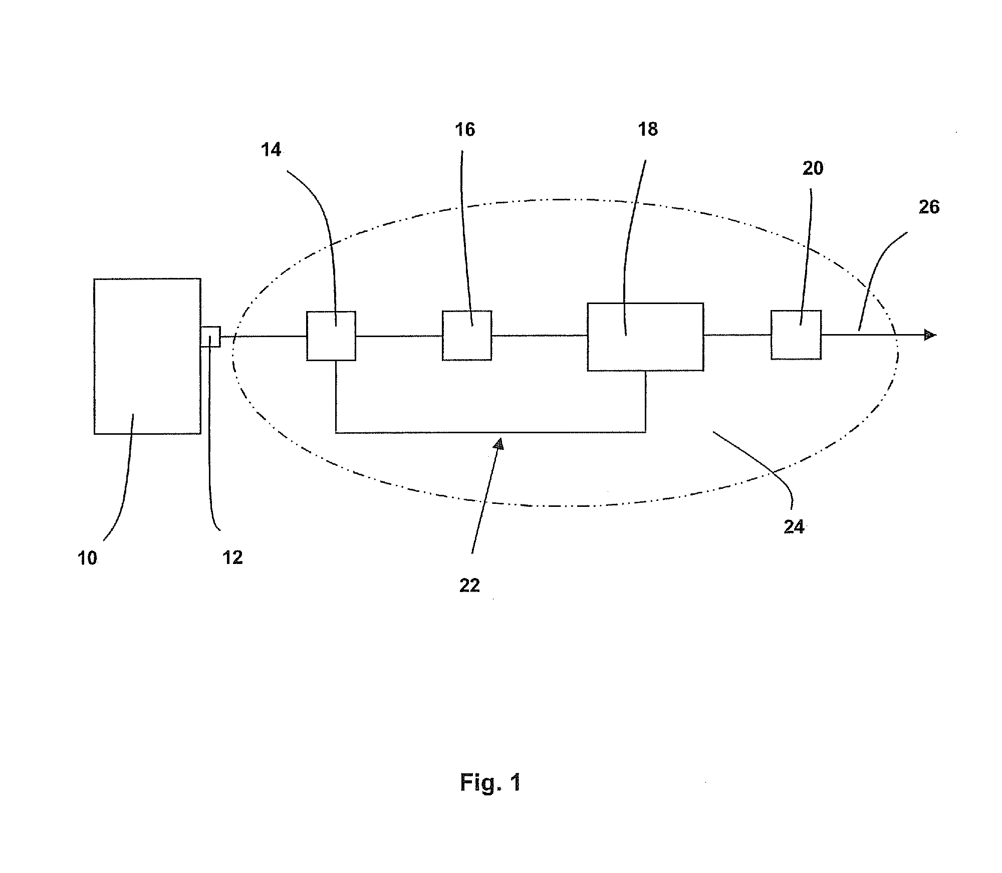
[0023]FIG. 1 is a schematic view of a knock detection device.

[0024]Knocking in a spark-ignition internal combustion engines occurs when combustion of the air / fuel mixture in the cylinder starts off correctly in a response to ignition by the spark plug, but one or more pockets of air / fuel mixture explode outside the envelope of the normal combustion front. The fuel-air charge is meant only to be ignited by the spark plug, and at a precise time in the piston's stroke cycle. When knock occurs, two or more combustion fronts will exist and their collisions produce a sudden rise in cylinder pressure and a shock-wave which will reverberate around the cylinder. This might damage the cylinder.

[0025]Shown in FIG. 1 are a combustion cylinder 10, a knock sensor 12 fixed to the walls of the combustion cylinder 10 and a knock detection device 24 which receives the signal from the knock sensor and provides a knock control signal 26.

[0026]The knock detection device includes a connection to the knoc...


PUM


Abstract

In the field of knock detection in a combustion engine, a method and a device detects and controls the knock by adapting the gain of an amplifier which amplifies the knock sensor signal. The gain of the amplifier is adapted based on analysis of a set of samples from the knock sensor so that the amplification of the knock sensor signal across the entire measuring window is optimum and the complete ADC evaluation range can be utilized better.

Description

CROSS-REFERENCE TO RELATED APPLICATIONS[0001]The present application claims priority to Application No. 08103844.0, filed in the European Patent Office on May 7, 2008, which is expressly incorporated herein in its entirety by reference thereto.FIELD OF THE INVENTION[0002]The present invention relates to the field of knock detection in combustion engines.BACKGROUND INFORMATION[0003]U.S. Pat. No. 6,529,817 describes a device for detecting a knock in a combustion engine.[0004]Conventionally, the amplifier used for amplifying the knock sensor signal has a fixed gain. As the knock sensor amplitude varies over a wide range, the amplification of the signal with a fixed gain will result in loss of resolution under some conditions.[0005]German Patent Document No. 102 20 600 describes a device in which the gain of the amplifier is adapted after processing the knock signal for knock detection.[0006]U.S. Pat. No. 5,040,510 describes a method in which the gain of the amplifier is stored as a fun...

Claims


Application Information

Patent Timeline
IPC IPC(8): G01L23/22
CPCF02D35/021F02D35/027Y02T10/46F02P5/1525G01L23/225F02D2041/1422Y02T10/40
Inventor BUGANZA, FEDERICOKLUTH, CARSTENTORNO, OSKARHAEMING, WERNER
Owner ROBERT BOSCH GMBH
Why Eureka
Try Eureka