Solar energy absorber

a solar energy absorber and solar energy technology, applied in the direction of solar radiation transmission, solar radiation prevention, light and heating apparatus, etc., can solve the problems of low pressure of discharged hot water, too heavy glass plate , /b>, etc., and achieve the effect of reducing weight and improving the external shape of solar energy absorbers

Inactive Publication Date: 2009-11-26
NISHIHARA HIDETABUGU
View PDF3 Cites 12 Cited by
  • Summary
  • Abstract
  • Description
  • Claims
  • Application Information

AI Technical Summary

Benefits of technology

[0035](6) since no water storing tank is required, the external shape of the solar energy absorber can be improved.
[0036]As described above, all of the problems of the conventional solar energy abso

Problems solved by technology

(1) the transparent glass plate 3 is too heavy to treat;
(2) as shown in FIG. 6, the stainless plates 9 are mutually adhered, so the plates 9 cannot fully resist water pressure, the plates 9 will be deformed if water pressure of tap water is directly applied thereto, therefore the water pressure must be received by the ball tap 6 and the plates 9 must be separated from the tap water;
(3) water is supplied to the water storing tank 5 by the ball tap 6, the discharged hot water is pressurized by only level difference between the water level in the water storing tank 5 and a level of a water faucet, so pressure of the discharged hot

Method used


Image

  • Solar energy absorber
  • Solar energy absorber
  • Solar energy absorber

Examples


example 1

[0051]Example 1 of the solar energy absorber relating to the present invention will be explained.

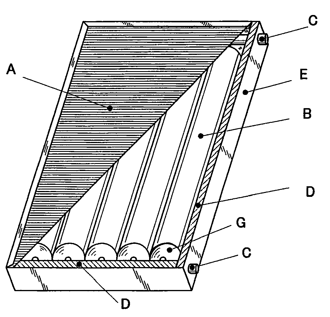
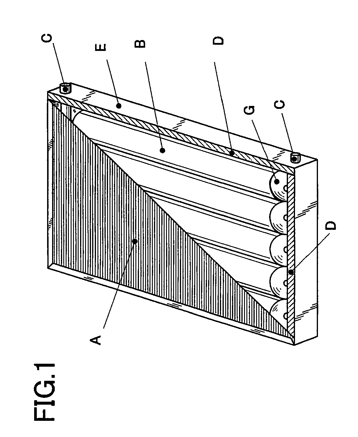
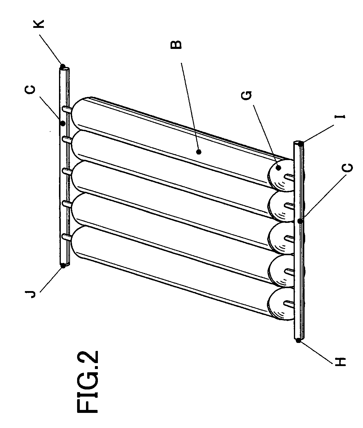
[0052]As shown in FIG. 2, five heat collection tubes B, each of which is composed of stainless steel and has a length of 900 mm, a thickness of 0.5 mm and a diameter of 70 mm, are arranged parallel. The funnel-shaped end plates G are bonded to the ends of the heat collection tubes B. The upper end plates G and the lower end plates G are respectively welded and connected to the header pipes C, so that the integrated water-flowing section can be formed.

[0053]Therefore, the entire water-flowing section has a tubular structure and can resist pressure of 1.0 Mpa, which is twice as high as an ordinary pressure of tap water, i.e., 0.5 Mpa. A capacity of the water-flowing section is about 20 liters.

[0054]The heat collection faces are respectively coated with the heat-absorbing layers by applying a black coating material or vacuum-depositing chrome layer thereon.

[0055]As shown in the sectional vi...

example 2

[0067]Example 2 of the solar energy absorber relating to the present invention will be explained with reference to FIG. 7. FIG. 7 is a transverse sectional view of the solar energy absorber.

[0068]The lower parts (the lower parts of the outer circumferential faces) of the heat collection tubes B contact a vacuum heat insulating material L.

[0069]Since the heat collection tubes B contact the vacuum heat insulating material L, the heat collection tubes B can be suitably held and heat transmission caused by the contact can be highly restrained. Therefore, the heat-retaining property of the solar energy absorber can be highly improved.

[0070]In Example 2, a bottom part of the heat-retaining box D, which is composed by a glass wool heat insulating material, is covered with the vacuum heat insulating material L. Further, inner faces of side walls of the heat-retaining box D are also covered with the glass wool heat insulating material. However, the structure of the heat-retaining box D is no...


PUM

PropertyMeasurementUnit
aaaaaaaaaa

Abstract

The solar energy absorber is capable of reducing weight, being directly connected to a water supply pipe, increasing pressure of heated water, omitting a pressurizing pump, etc. The solar energy absorber comprises: a water-flowing section including heat collection tubes, which are composed of stainless steel, and connecting pipes; a heat-retaining box accommodating the water-flowing section, including a heat insulating material and having an opening part which is located on the heat collection side; and a cover plate being composed of a transparent multilayer plastic and closing the opening part of the heat-retaining box. The heat collection tubes are arranged parallel. End plates closing ends of the heat collection tubes are connected to the connecting pipes. Each of the heat insulating tubes is coated with a heat-absorbing layer. Parts of the heat collection tubes which are located on the opposite side of the heat collection side contact the heat insulating material.

Description

CROSS-REFERENCE TO RELATED APPLICATION[0001]This application is based upon and claims the benefit of priority of the prior Japanese Patent Application No. P2008-158507, filed on May 21, 2008, and the prior Japanese Patent Application No. P2008-235241, filed on Sep. 12, 2008, the entire contents of which are incorporated herein by reference.FIELD OF THE INVENTION[0002]The present invention relates to a solar energy absorber capable of heating water with solar energy.BACKGROUND OF THE INVENTION[0003]A conventional solar energy absorber is shown in FIG. 5. A cover plate 3 is a transparent glass plate. A heat collection section 1 is constituted by a plurality of stainless plates 9, which are mutually adhered. An inner bottom face and inner side faces are covered with an insulating material 4 composed of glass wool so as to keep temperature. The solar energy absorber is partially covered with a metal plate 2 and connected to a water storing tank 5, which is composed of polyethylene and c...

Claims


Application Information

Patent Timeline
IPC IPC(8): F24J2/04F24S10/70
CPCF24J2/507F24J2002/502F24J2/4652F24J2/245Y02E10/44F24S70/30F24S2080/502F24S10/742F24S80/54
Inventor NISHIHARA, HIDETSUGU
Owner NISHIHARA HIDETABUGU
Why Eureka
Try Eureka