Vehicle with multiple engines coupled to a transmission via a jackshaft

a technology of transmission and jackshaft, applied in the field of vehicles, can solve the problems of substantial design and development costs, and substantial design, tooling, fabrication and testing costs, and achieve the effect of reducing operating costs

Inactive Publication Date: 2009-11-26
BELLOSO GREGORIO M
View PDF19 Cites 26 Cited by
  • Summary
  • Abstract
  • Description
  • Claims
  • Application Information

AI Technical Summary

Benefits of technology

[0018]e) economy of operation is achieved by deactivating one engine when lesser power is needed for propulsion of the vehicle.
[0021]The primary engine may be made to have about ½ to ⅓ the size and power capacity of the auxiliary engine to maximize fuel economy while cruising with minimum load, and to maximize performance in acceleration and other heavy duty capacity. Furthermore, each engine may be coupled to the jackshaft via a free-wheeling clutch, such as a sprag clutch, so that it becomes possible to choose to power the vehicle with only the primary engine for light duty operation (e.g., for cruising with minimum load), or with only the auxiliary engine for medium duty operation (e.g., for cruising when fully loaded), and with power from both the primary engine and the auxiliary engine for maximal acceleration or heavy duty operation.

Problems solved by technology

Prior vehicles using multiple engines have problems related to the need to design and fabricate new transmission components and even to design entirely new engine blocks and parts thereof to result in a useful product.
These requirements entail substantial expenditure of time, technical expertise and financial resources for the design, fabrication, testing and manufacturing of essentially new and untested technology which will then need to be perfected and made reliable to be profitably marketable.
It is not amenable to the use of an unmodified speed change gearbox.
It requires a totally new design of a speed change gearbox which would entail substantial design and development costs and then extensive reliability testing before it can be marketable.
This would call for substantial design, tooling, fabrication and testing costs before it can be ready for mass manufacture.

Method used


Image

  • Vehicle with multiple engines coupled to a transmission via a jackshaft
  • Vehicle with multiple engines coupled to a transmission via a jackshaft
  • Vehicle with multiple engines coupled to a transmission via a jackshaft

Examples


Embodiment Construction

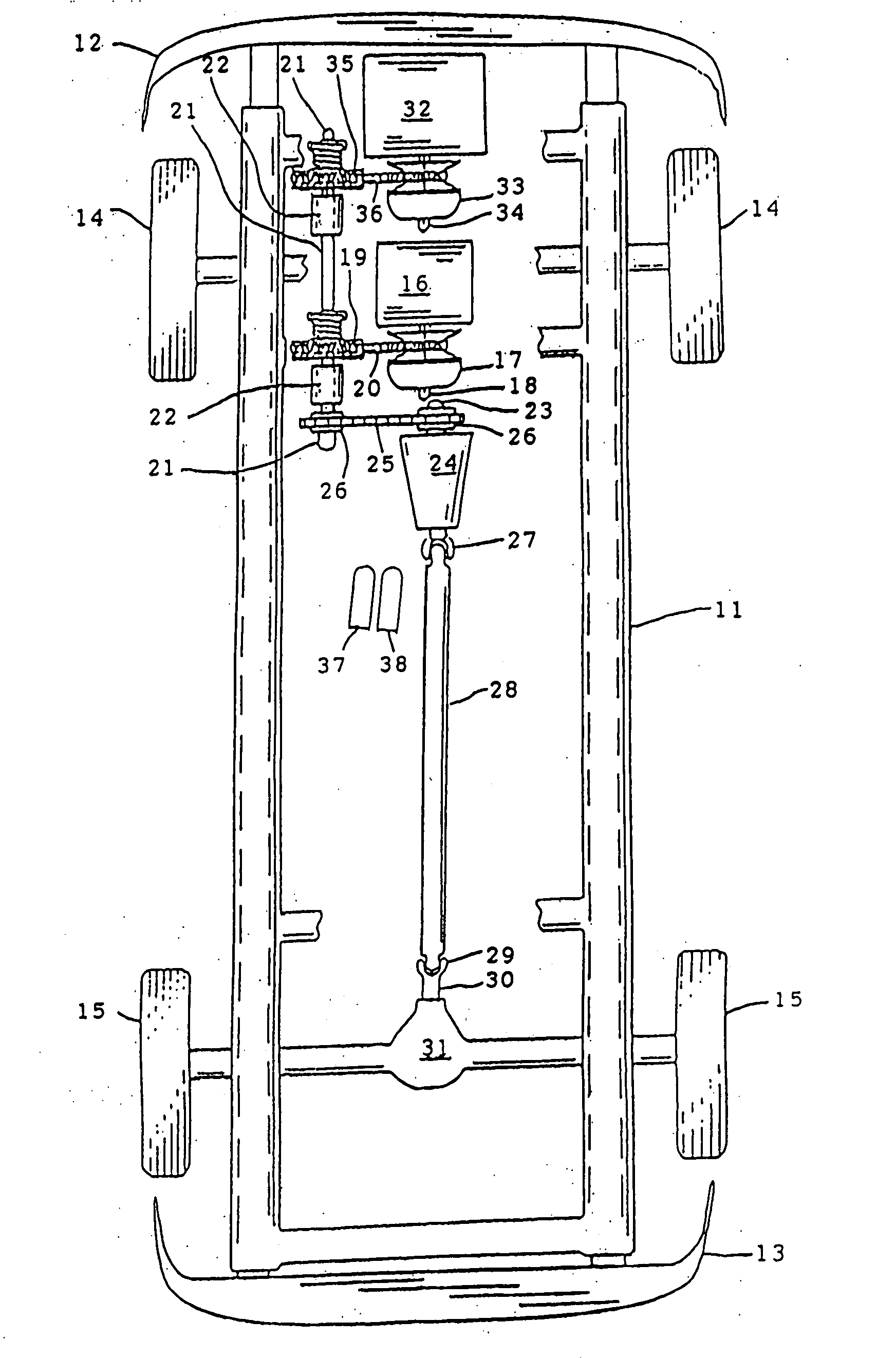
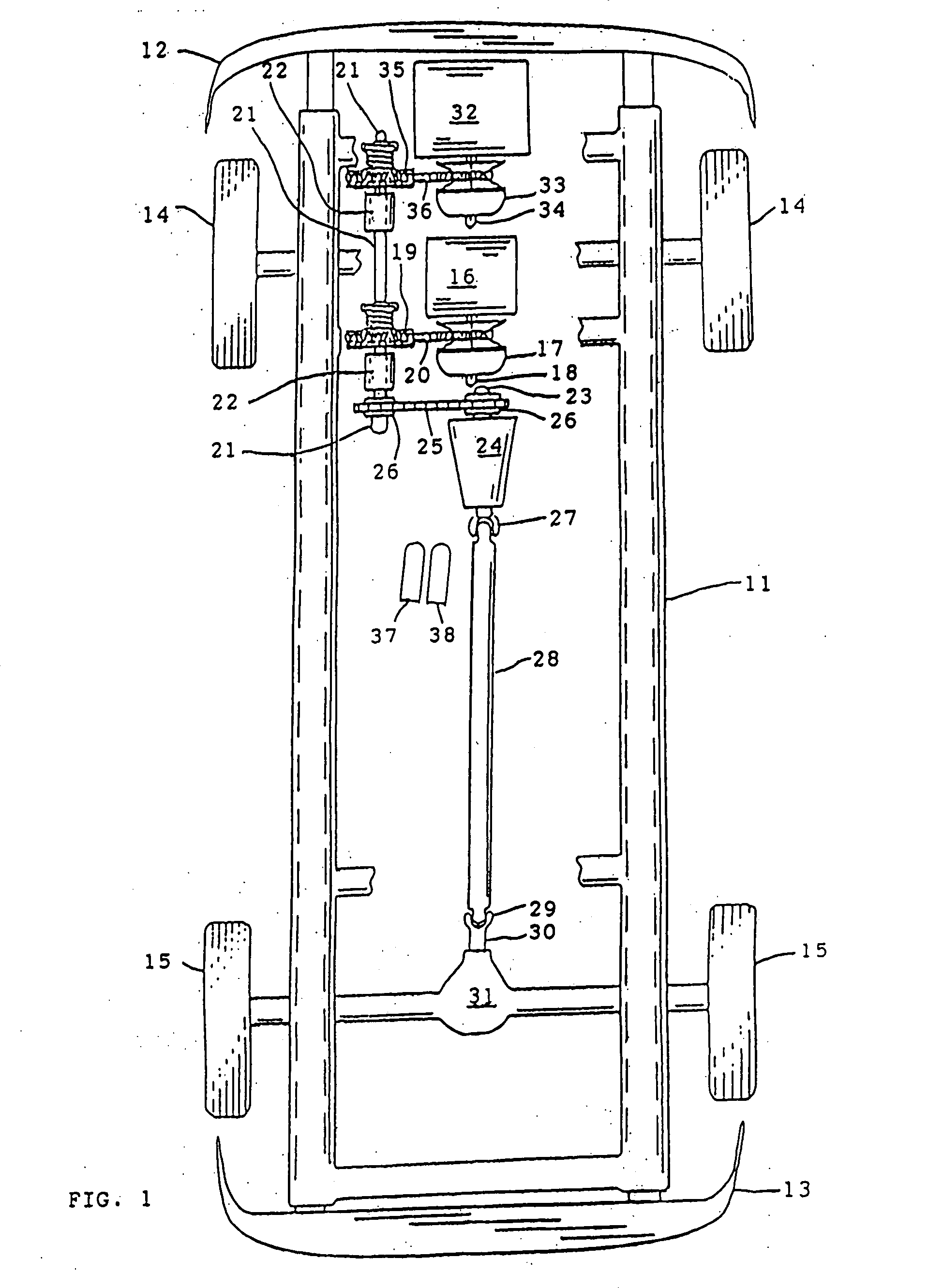
[0033]Referring now to the drawings wherein one character designates one part of the vehicle, FIG. 1 shows a vehicle of the present invention having a chassis 11 connected to front bumper 12 and rear bumper 13, and supported by paired front wheels 14 and paired rear wheels 15.

[0034]A power train is shown comprised of primary “cruiser” engine 16 mounted on chassis 11. Primary CVT driver pulley 17 is mounted on output shaft 18 of said primary engine, and is connected to primary CVT driven pulley 19 by drive belt 20. Driven pulley 19 is fixedly mounted on jackshaft 21 which is rotatably journaled on bearings 22 which are anchored on chassis 11. Jackshaft 21 is connected to input shaft 23 of speed change transmission 24 via chain 25 and sprockets 26. Power from speed change transmission 24 is conveyed via front universal joint 27, propeller shaft 28, rear universal joint 29, pinion 30, and differential 31 to the rear wheels 15 to drive the vehicle.

[0035]The size and power capacity of pr...


PUM


Abstract

A motor vehicle is provided with a power train having primary and auxiliary internal combustion engines which selectively feed power to a jackshaft. The power accumulated in the jackshaft is conveyed to a speed change transmission. Fuel economy is achieved by utilizing only one engine when lesser power is needed by the vehicle.

Description

BACKGROUND OF THE INVENTION[0001]1. Field of the Invention[0002]This invention relates to a vehicle having multiple internal combustion engines whose power output can be combined and routed to a transmission for the purpose of improving fuel efficiency and accommodating the power needs of the vehicle.[0003]2. Description of the Prior Art[0004]Increasing greenhouse gas emissions to the atmosphere and the increasing cost of fossil fuels have driven the search for means to improve automotive fuel efficiency. One solution has been the hybrid automobile which uses a small fuel-efficient internal combustion engine augmented by a battery-driven electric motor to power the vehicle. Another solution uses two or more internal combustion engines, using their combined power for acceleration, climbing steep grades, etc., and using the power of one engine to cruise economically.[0005]The present invention relates to the latter solution, using multiple engines for acceleration, and using one engin...

Claims


Application Information

Patent Timeline
Patent Type & Authority Applications(United States)
IPC IPC(8): B60K5/08
CPCB60K1/02B60K5/08B60K6/442B60K6/46B60K6/543Y02T10/6286B60W10/08B60W20/00B60W2540/10Y02T10/6217Y02T10/6234B60W10/06Y02T10/62B60W20/15
Inventor BELLOSO, GREGORIO M.
Owner BELLOSO GREGORIO M
Why Eureka
Try Eureka