Adaptive rate control for feeding grain to a grain unloader conveyor

a technology of unloading conveyor and adaptive rate control, which is applied in the direction of loading/unloading vehicle arrangment, transportation and packaging, transportation items, etc., can solve the problems of reducing the working life of components, reducing the efficiency of vertical unloading auger, and excessive start up torque of loaded conveyors, so as to avoid high start up torque spiking, the effect of little or no capacity for receiving additional grain

Active Publication Date: 2009-11-26
BLUE LEAF I P INC
View PDF17 Cites 28 Cited by
  • Summary
  • Abstract
  • Description
  • Claims
  • Application Information

AI Technical Summary

Benefits of technology

[0012]According to another preferred aspect of the invention, the automatic sensing of the at least one condition is done while momentarily initiating the operation of the apparatus, to determine an initial capacity of the unloader to receive the grain, and the step of automatically controllably operating the apparatus comprises subsequently operating the apparatus at a rate which is a function of the determined initial capacity. As an example, the sensed condition can be a pressure condition resulting from the initial momentary operation of the apparatus. This can be done simultaneous with initiation of operation of the unloader conveyor, or after a brief pause or delay to avoid high start up torque spiking. The sensed condition can also / alternatively comprise a speed of operation. And, if an alternative drive is employed, the sensed condition or conditions can include an electrical characteristic such as a current value in the instance of an electrical motor drive, or a strain condition or measured torque or force in the instance of a mechanical drive, to name just a few alternatives. In the instance wherein the sensed condition is a pressure, if the inlet region of the unloader conveyor contains a large quantity of grain, so as to have little or no capacity for receiving additional grain, and / or the apparatus itself contains substantial grain, the pressure condition will be high (speed will be low), as the grain being fed to the unloader will be at least momentarily forced against the grain in the inlet region. On the other hand, if the inlet region is empty, or is less than full, and / or the apparatus itself is less than full, the pressure condition will be lower (and the speed higher), thus representing available capacity, and the ability to receive grain. In the instance of an electrical drive, the current value will be greater for a higher torque condition, and in the instance of a mechanical drive, strain or measured torque will be greater. Thus, by sensing the condition or conditions at start up of the apparatus, namely high start up torque, possible grain damage, and the like, can be avoided.
[0013]According to another preferred aspect of the invention, the at least one condition can be sensed periodically, or continuously during operation of the unloader conveyor, to determine the grain receiving capacity, and the operation of the apparatus, particularly, the rate of feeding of the grain to the unloader conveyor, adapted or adjusted as a function of the capacity, on an ongoing, real time or near real time basis, in a feed back loop. As a result, the rate of grain feed to the unloader conveyor can be substantially matched to the capacity of the unloader to receive the grain, such that economy and efficiency of the unloading operation can be improved or maximized.

Problems solved by technology

This simultaneous action causes several issues, namely, one can only operate the system at a maximum unload or discharge rate, and, in situations in which the system is halted in the loaded condition, start up torques of a loaded conveyor can be excessive and result in failure.
A reason for this is that the vertical unloader auger is typically more inefficient and takes longer to empty than a horizontal auger.
Another reason would be to eliminate the subsequent gross start up torque and power requirements, which, as noted above, can reduce the working life of components due to early failure, and can require higher product cost.
Additionally, after use, if the unloader conveyor is not cleaned out, remaining grain has been observed to have a tendency to settle in the enclosed lower region of the vertical unloader conveyor around the lower end of the auger therein and the adjacent end of the cross conveyor adjacent to the inlet opening.
As a result, an additional problem that can occur if the cross conveyor and unloader conveyor are started simultaneously, or the cross conveyor is started first, is that the cross conveyor can force or pack the grain into and against the grain in the lower unloader conveyor housing, thereby causing grinding, cracking of, and other damage to the grain.
Additionally, no provision is provided for controlling operation for topping off and the like.

Method used


Image

  • Adaptive rate control for feeding grain to a grain unloader conveyor
  • Adaptive rate control for feeding grain to a grain unloader conveyor
  • Adaptive rate control for feeding grain to a grain unloader conveyor

Examples


Embodiment Construction

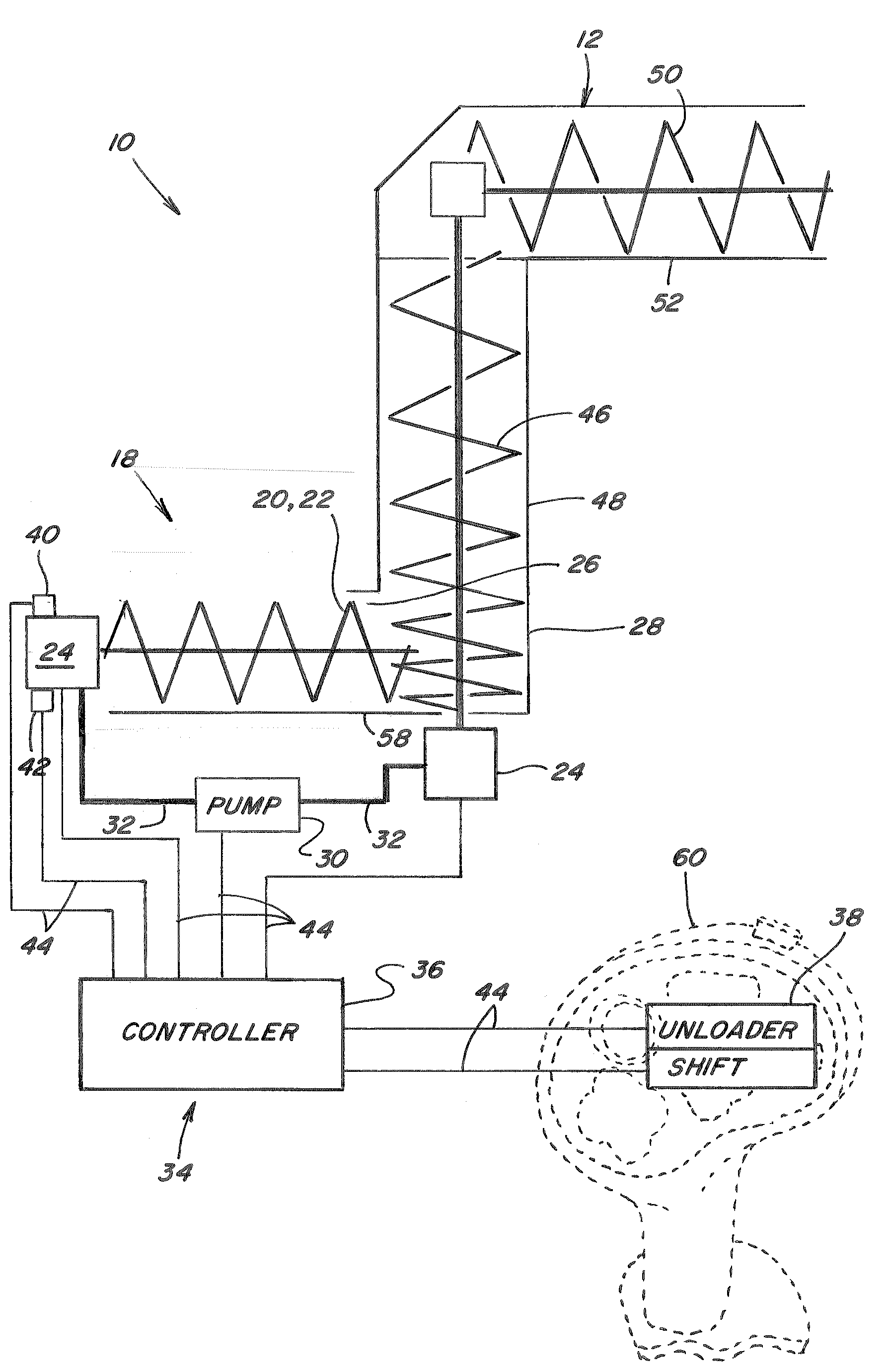
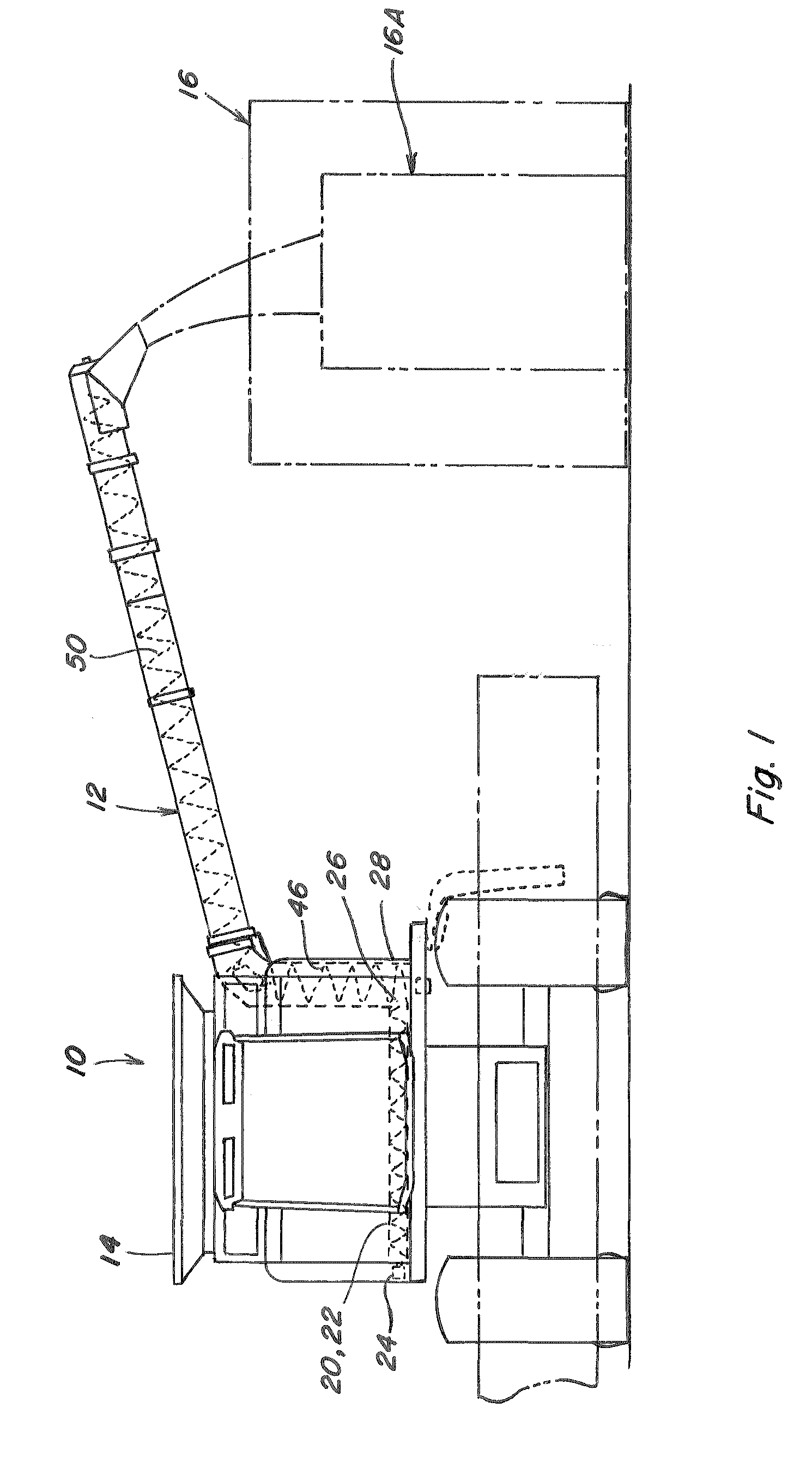
[0024]Referring now the drawings, in FIG. 1, a representative agricultural harvesting machine 10 is shown, including an unloader conveyor 12 operable for unloading grain from a grain holding device, which is a conventional grain tank 14, located on an upper region of harvesting machine 10. Here, harvesting machine 10 is depicted as a well known, commercially available combine operable for harvesting a wide variety of grains, including, but not limited to, wheat, beans, corn, rice, and the like. Typically, the grain is harvested and threshed from stalks, pods, or other crop material, and conveyed away from a cleaning system of machine 10 by a clean grain conveyor to a grain elevator (not shown). The grain elevator then lifts the grain upwardly to a grain delivery conveyor which is operable for discharging the grain into grain tank 14. When grain tank 14 is filled with grain, or filled to a desired level, unloader conveyor 12 can be operated for unloading the grain from tank 14, onto ...


PUM


Abstract

The control of an apparatus within a grain holding device for feeding grain to an unloader conveyor operable for conveying the grain from the holding device, includes sensing a predetermined condition or conditions representative of capacity of the unloader conveyor for receiving grain, and adaptively controlling the apparatus for feeding grain to the unloader conveyor in advantageous varying manners responsive to the conditions, including to delay initiation of feeding until the receiving capacity is increased, and to match the grain feed to the capacity. The automatic control can be overridden, to allow user control of unloader speed, and can be configured to allow cleanout of the unloader conveyor.

Description

[0001]This application claims the benefit of U.S. Provisional Patent Application Ser. No. 61 / 128,483 filed May 22, 2008.TECHNICAL FIELD [0002]This invention relates generally to control of an apparatus within a grain holding device for feeding grain to an unloader conveyor operable for conveying the grain from the holding device, and more particularly, to sensing a predetermined condition or conditions representative of capacity of the unloader conveyor for receiving grain, and adaptively controlling the apparatus for feeding grain to the unloader conveyor in advantageous varying manners responsive to the conditions.BACKGROUND OF THE INVENTION [0003]U.S. Provisional Application No. 61 / 128,483, filed May 22, 2008, is incorporated herein in its entirety by reference.[0004]Current grain holding systems, such as combine grain tank unloading systems of combine harvesters, typically consist of single or multiple apparatus, typically, a cross conveyor or conveyors, that feed grain to an un...

Claims


Application Information

Patent Timeline
Patent Type & Authority Applications(United States)
IPC IPC(8): B65G43/00A01D61/00B60P1/42A01D41/12B65G65/46
CPCB60P1/42A01D41/1217
Inventor FARLEY, HERBERT M.YOUNG, STEVEN C.WARD, KEVIN W.HOLT, II, EDMUND N.FREGO, JEFFREY D.ANDERSON, BRUCE E.
Owner BLUE LEAF I P INC
Why Eureka
Try Eureka