Variable-Speed-Drive System for a Grid Blower

a technology of variable speed and blower, which is applied in the direction of temperatue control, starter details, special data processing applications, etc., can solve the problems of increased noise, vibration, harshness, and equipment stress,

Active Publication Date: 2009-12-03
GE GLOBAL SOURCING LLC
View PDF7 Cites 21 Cited by
  • Summary
  • Abstract
  • Description
  • Claims
  • Application Information

AI Technical Summary

Problems solved by technology

However, various issues may arise with the above described configuration.
As another example, the blower accelerates at a high rate whenever electrical power is suddenly applied to the grid of resistive elements, thereby producing high transients which may result in increased noise, vibration, harshness, and stress on the equipment.

Method used


Image

  • Variable-Speed-Drive System for a Grid Blower
  • Variable-Speed-Drive System for a Grid Blower
  • Variable-Speed-Drive System for a Grid Blower

Examples


Embodiment Construction

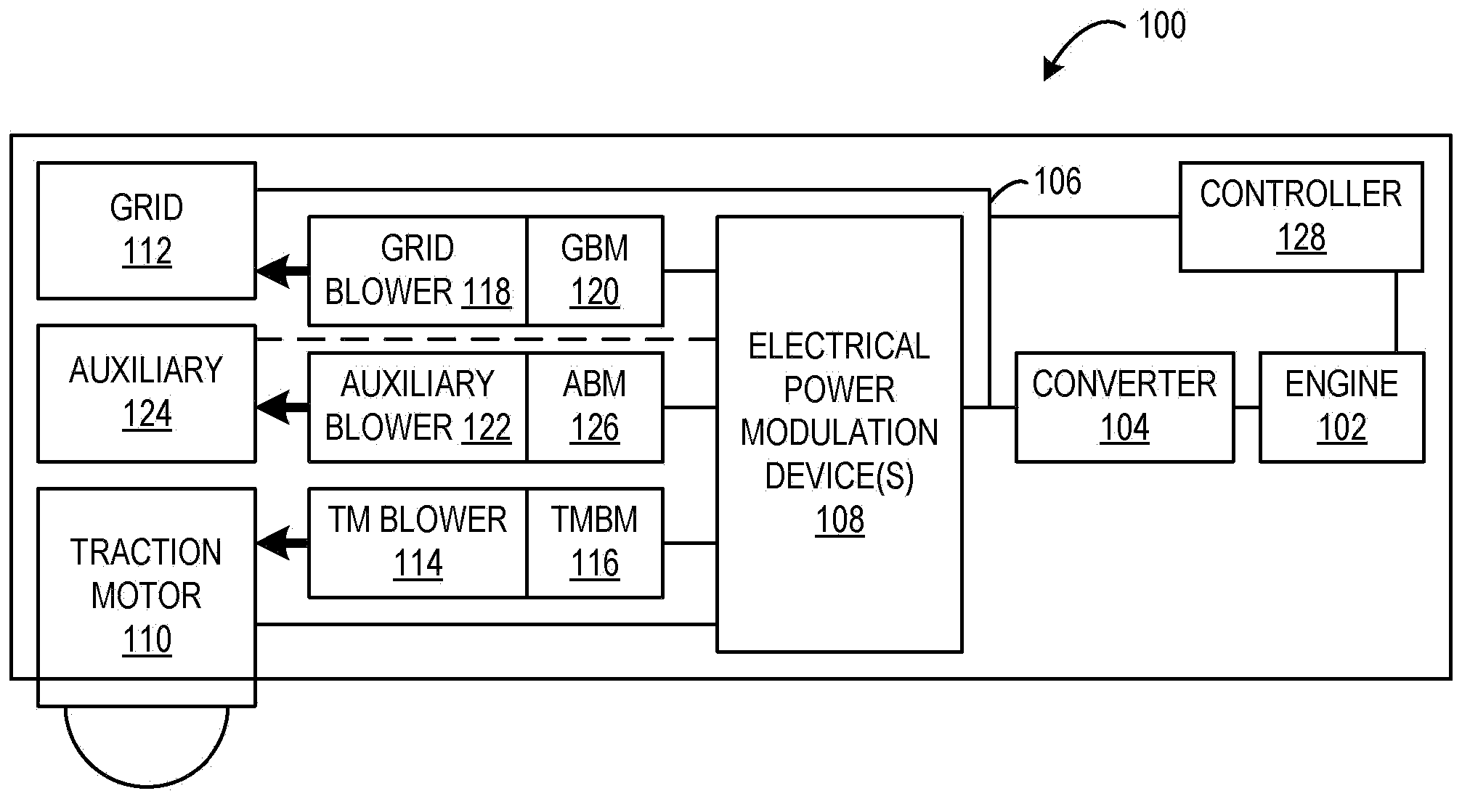
[0019]The subject matter disclosed herein generally relates to propulsion systems utilizing tractive effort. In particular, the subject matter relates to mechanisms that may be utilized to aid in heat dissipation from electrical power dissipation grids of a locomotive vehicle having traction motors. FIG. 1 schematically shows an example of a locomotive vehicle system 100. Typically, the locomotive vehicle system may be a diesel-electric locomotive that includes a diesel engine. However, it will be appreciated that engine configurations other than a diesel engine may be implemented in the locomotive vehicle system, such as a gasoline engine, for example. In some embodiments, the locomotive vehicle system may be powered by way-side power and the engine may be omitted (e.g., electric locomotives).

[0020]The locomotive vehicle system 100 includes an engine 102 that may be configured to generate torque output that drives a converter 104. The converter 104 may produce electrical power that...


PUM


Abstract

A drive system for a grid blower of a vehicle is provided. The system includes: an electrical bus, a grid of resistive elements connected to the electrical bus, the grid of resistive elements configured to thermally dissipate electrical power generated from braking of the vehicle, the electrical power being transmitted on the electrical bus to the grid of resistive elements, an electrical power modulation device configured to modify electrical power received from at least one of the electrical bus and the grid of resistive elements, and a grid blower motor coupled to an output of the electrical power modulation device, wherein a speed of the grid blower motor varies based on the electrical power that has been modified by the electrical power modulation device.

Description

BACKGROUND[0001]A propulsion system may include one or more traction motors to generate tractive output. For example, a propulsion system having one or more traction motors may be utilized in an off-highway vehicle (OHV) application, locomotive application, a marine application, a drilling application, etc. In one example, a locomotive vehicle having traction motors may perform dynamic braking in conjunction with air braking in order to slow the locomotive vehicle. By utilizing dynamic braking, the brake load on the air brakes may be reduced which, in turn, may reduce the wear on the air brakes thus extending their useful life.[0002]During dynamic braking operations, the traction motors may generate electrical power that may be transmitted to a grid of resistive elements which may dissipate the electrical power in the form of heat. As dynamic braking operations are performed, the temperature of the grid of resistive elements may increase. Accordingly, a blower may be utilized to pro...

Claims


Application Information

Patent Timeline
Patent Type & Authority Applications(United States)
IPC IPC(8): B61C5/02H02P3/14H02P31/00B60L50/11
CPCB60L1/003B60L7/02B60L2200/26B61C5/02B60L7/10
Inventor KUMAR, AJITH KUTTANNAIRWORDEN, BRETGUPTA, SUDHIR KUMARBROWN, THEODORE CLARK
Owner GE GLOBAL SOURCING LLC
Why Eureka
Try Eureka