
Detonation Combustor Cleaning Device and Method of Cleaning a Vessel with a Detonation Combustor Cleaning Device

a technology of combustor cleaning and detonation combustor, which is applied in the direction of machines/engines, combustion types, lighting and heating apparatus, etc., can solve the problems of reducing fuel efficiency, generating residues from burning fuel, and reducing performan

Inactive Publication Date: 2009-12-03
BARRETO INVESTMENT GRP INC
View PDF7 Cites 13 Cited by
  • Summary
  • Abstract
  • Description
  • Claims
  • Application Information

AI Technical Summary

Benefits of technology

"The invention is a detonation device cleaning system that includes a vessel, a fuel source, an air source, and a detonation combustor cleaning device. The deto combustor cleaning device includes a combustion chamber, a deflection member, an air inlet, a fuel inlet, and an ignition device. The system is designed to produce a shockwave that impacts the inner surface of the vessel to dislodge particles clinging to it. The invention also includes a method of cleaning a vessel with the deto combustor cleaning device. The technical effects of the invention include improved cleaning efficiency and reduced downtime for maintenance."

Problems solved by technology

Burning fuel may generate residues that often are left behind forming a buildup on surfaces of associated ducting or heat exchanger.
This buildup can lead to performance degrades related to an increase in pressure drop, reduced fuel efficiency, and damage to mechanical components.
These performance degrades can eventually lead to costly planned or unplanned outages.
However, such systems are often times costly to maintain and not always effective.
Detonative combustion devices that burn customer friendly fuels, such as natural gas and propane, tend to require large detonation chamber diameters and lengths, which, in turn, require a relatively large installation footprint.
Moreover, in some cases, such detonation devices require oxygen enrichment in order to create the detonations.
Flexible fuels, or fuels having a large detonation cell size and high direct initiation energy, such as natural gas and propane, do not burn properly in existing systems without the addition of some amount of pre oxygen.
More specifically, when using flexible fuels in existing detonative combustions devices, flame propagation velocity is less than desired, resulting in little or no cleaning ability o the resulting combustion process.

Method used


Image

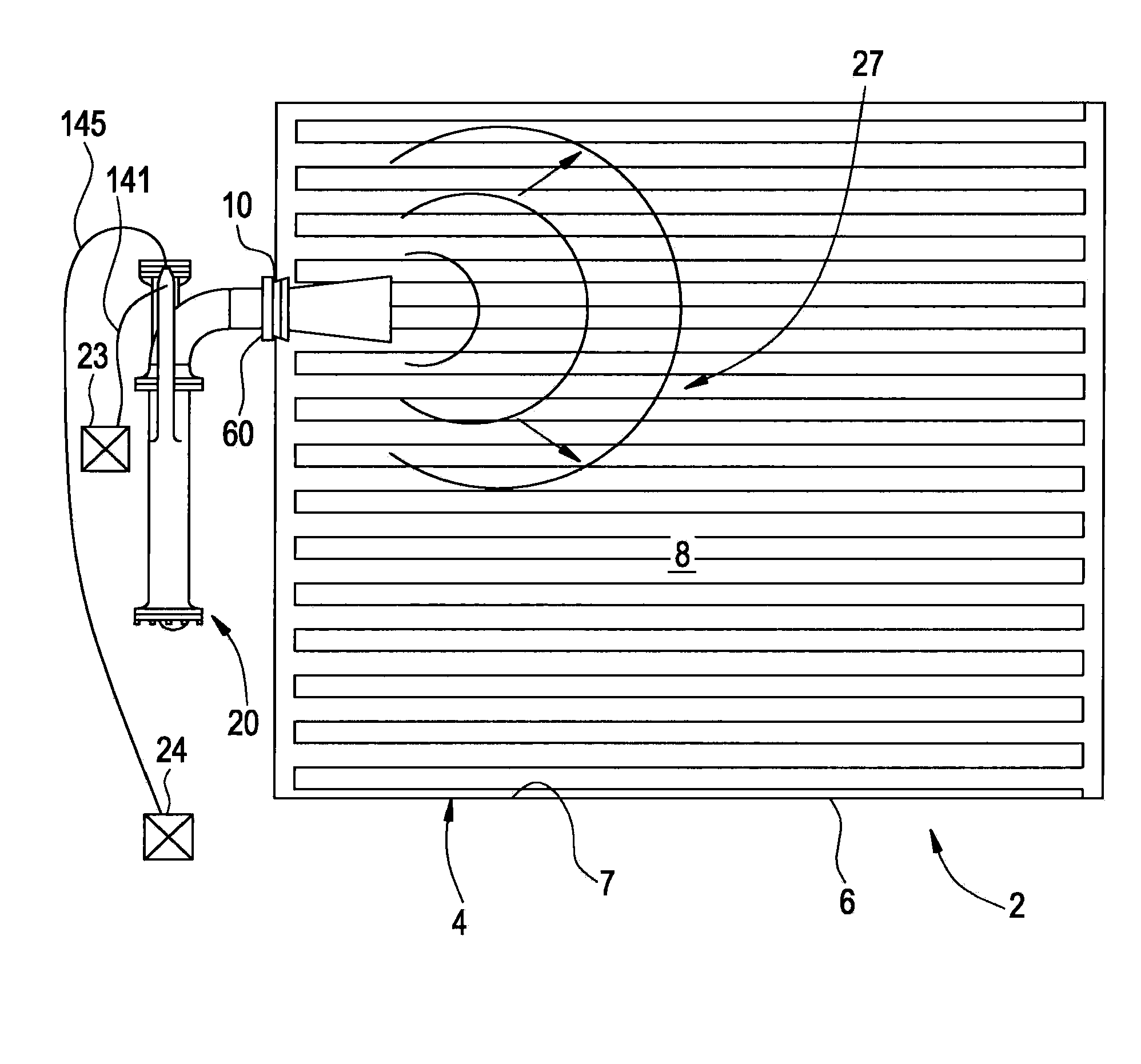
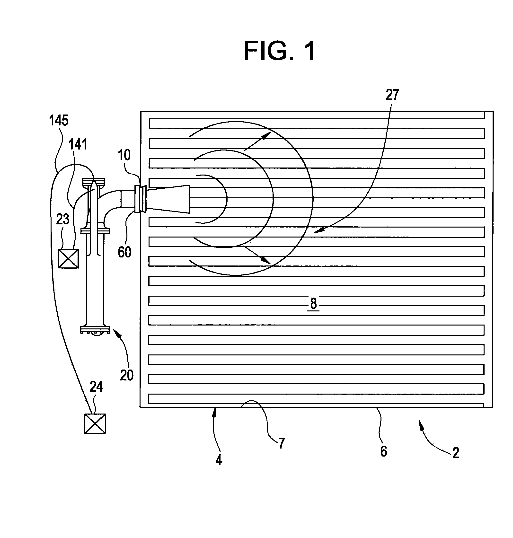
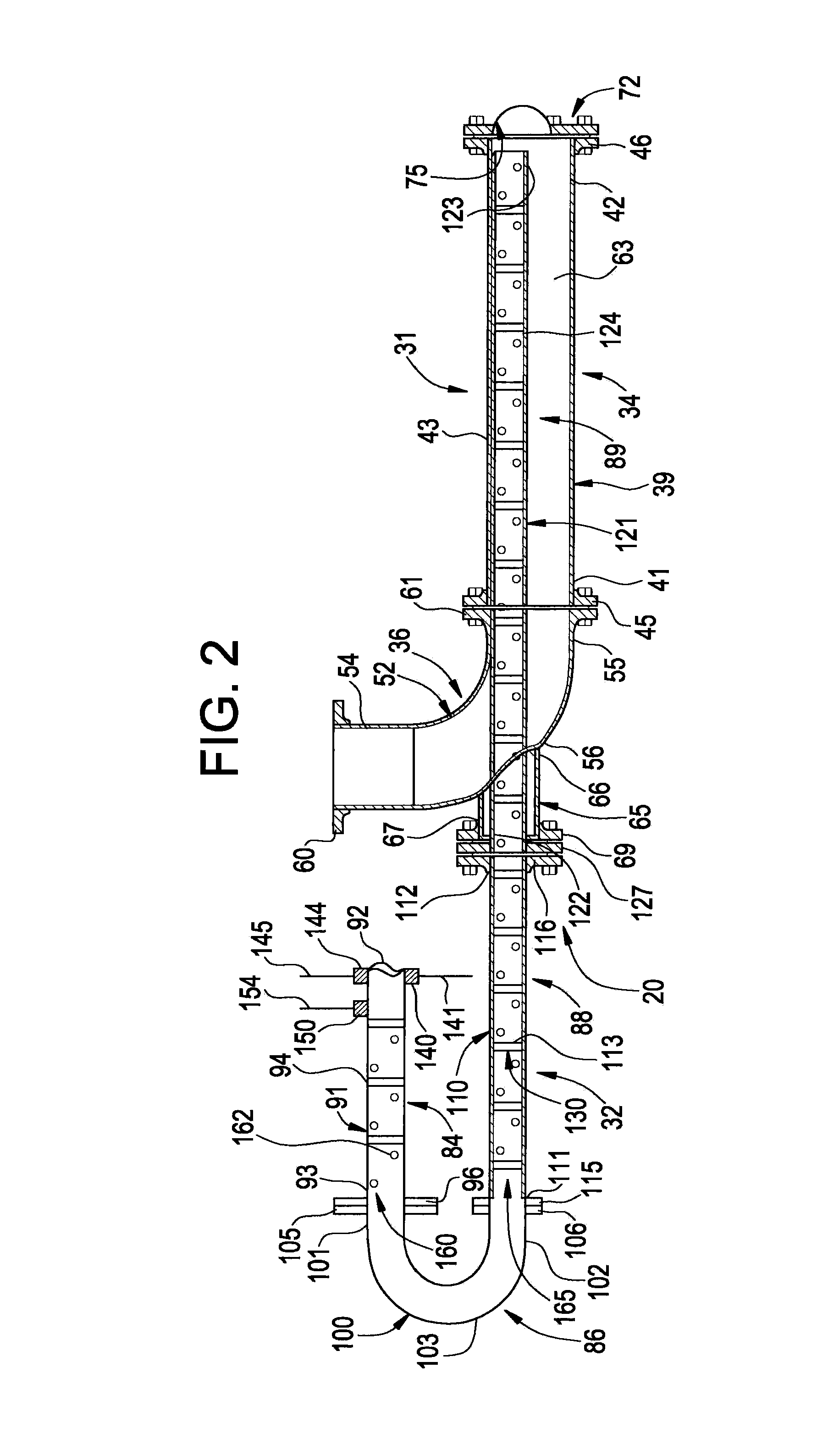
  • Detonation Combustor Cleaning Device and Method of Cleaning a Vessel with a Detonation Combustor Cleaning Device
  • Detonation Combustor Cleaning Device and Method of Cleaning a Vessel with a Detonation Combustor Cleaning Device
  • Detonation Combustor Cleaning Device and Method of Cleaning a Vessel with a Detonation Combustor Cleaning Device

Examples


Embodiment Construction

[0011]Soot, ash, or other buildup on inner surfaces of industrial boilers or other vessels can cause efficiency losses. Examples of such efficiency losses include reduced heat transfer capability, reduced gas flow capability and reduced process “online” time. In the case of industrial boilers, the efficiency losses are often evidenced by an increase in exhaust gas temperature measured at a backend of a heat exchange process, as well as an increase in a fuel-burn rate necessary to maintain steam production and energy output. Traditionally, completely removing buildup from such fouled surfaces requires that the boiler be shut down during cleaning. Some online cleaning methods are able to extend boiler operation without localized cleaning. Cleaning while the boiler remains online generally leads to high maintenance costs, high operation costs and / or incomplete cleaning results.

[0012]In the systems and techniques according to exemplary embodiments of the invention, a combustion chamber ...


PUM


Abstract

A detonation combustor cleaning device includes at least one combustion chamber having combustion flow path and including a deflection member. An ignition device is operatively connected to the at least one combustion chamber is selectively activated to ignite a combustible fuel within the at least one combustion chamber to produce a shockwave that moves in a first direction along the combustion flow path, impacts the deflection member, reverses direction and passes into a vessel to dislodge particles clinging to inner surfaces thereof.

Description

BACKGROUND[0001]The present disclosure relates to the art of vessel cleaning devices and, more particularly, to a detonation combustor cleaning device for dislodging debris from inner surfaces of vessels.[0002]Industrial boilers operate by using a heat source to create steam from water or another working fluid, which can then be used to drive a turbine in order to supply power. Conventionally, the heat source is a combustor that burns a fuel in order to generate heat, which is then transferred into the working fluid via a heat exchanger, such as a fluid conducting tube or pipe. Burning fuel may generate residues that often are left behind forming a buildup on surfaces of associated ducting or heat exchanger. This buildup can lead to performance degrades related to an increase in pressure drop, reduced fuel efficiency, and damage to mechanical components. These performance degrades can eventually lead to costly planned or unplanned outages. Periodic removal or prevention of such buil...

Claims


Application Information

Patent Timeline
Patent Type & Authority Applications(United States)
IPC IPC(8): F28G11/00
CPCB08B7/0007F28G7/005F28G7/00F23J3/023F23J3/00F28G11/00F28G13/00
Inventor DEAN, ANTHONY JOHNCHAPIN, DAVID MICHAELCREAR, DONNELL EUGENE
Owner BARRETO INVESTMENT GRP INC
Learn More