Power control unit and hybrid vehicle comprising same

Active Publication Date: 2009-12-03
HONDA MOTOR CO LTD
View PDF13 Cites 48 Cited by
  • Summary
  • Abstract
  • Description
  • Claims
  • Application Information

AI Technical Summary

Benefits of technology

[0010]Hence an object of the present invention is to provide a power control unit which can be reduced in size, the conduc

Problems solved by technology

However, in such a conventional semiconductor module, connections employ wire bonding, so there are problems in that a large amount of space is necessary for wire distribution and a large occupied area must be secured for the semiconductor module.
In addition, the conduction resistance increases due to the fact that a wire is used, so there is a problem in that electrical losses increase.
Also, there are problems in that much manufacturing time is required and manufacturing costs moun

Method used


Image

  • Power control unit and hybrid vehicle comprising same
  • Power control unit and hybrid vehicle comprising same
  • Power control unit and hybrid vehicle comprising same

Examples


Example

[0037]Next, embodiments of the present invention are explained based on the drawings.

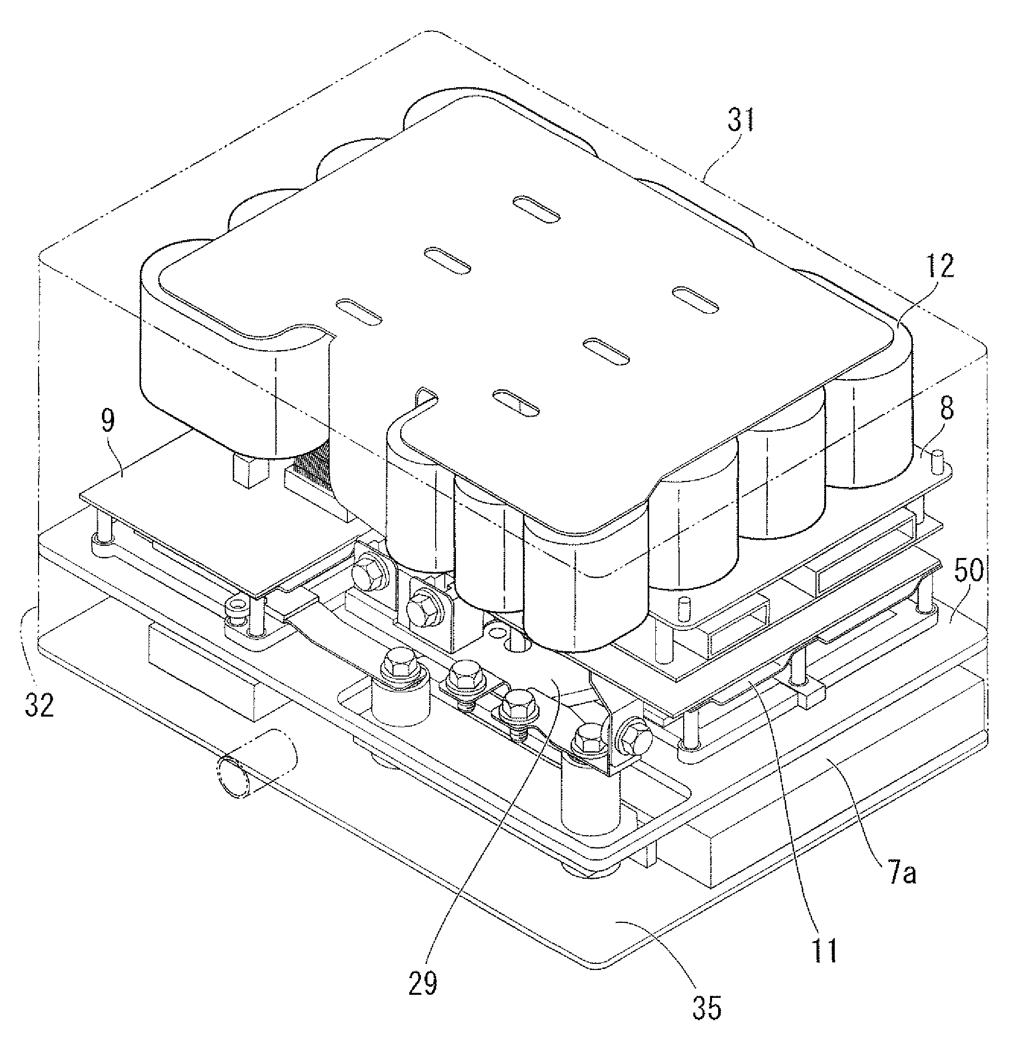
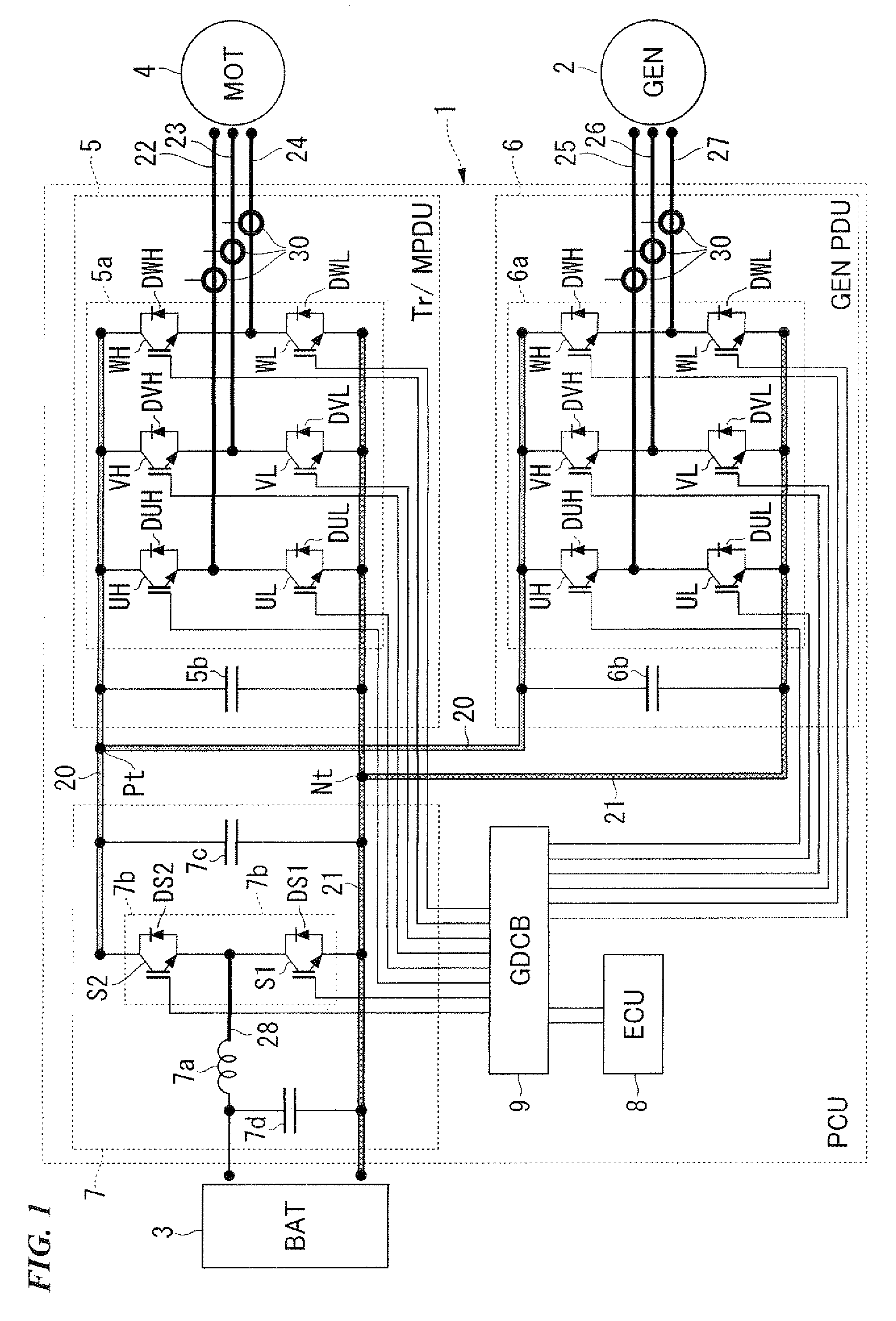
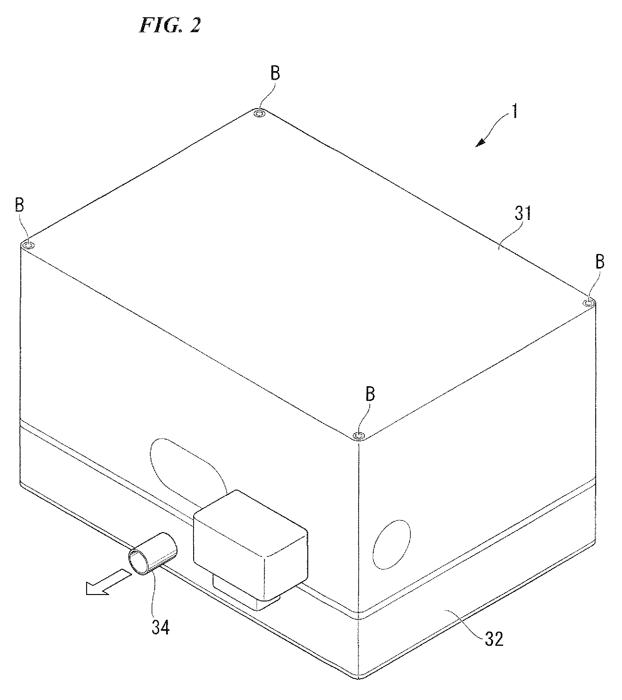
[0038]FIG. 1 shows a circuit configuration comprising a power control unit (PCU) 1 for a hybrid vehicle. This hybrid vehicle includes an engine (not shown), an electric generator (GEN) 2 which is driven by the mechanical output of the engine, a high-voltage battery (BAT) 3 which is charged by the electrical power output of the electric generator 2, and a motor (MOT) 4 which drives drive wheels (not shown) using at least one of the discharge output of the battery 3 and the electric power output of the electric generator 2.

[0039]The power control unit 1 comprises a first inverter (Tr / M PDU) 5 and a second inverter (GEN PDU) 6. The first inverter 5 drives the motor 4 via a converter 7 which functions as a voltage step-up circuit using electric power supplied from the battery 3, and also supplies electric power to the battery 3 via the converter 7 which functions as a voltage step-down circuit when the ...


PUM


Abstract

A power control unit which comprises a plurality of semiconductor elements including a plurality of high-potential side semiconductor elements and a plurality of low-potential side semiconductor elements, and each having a first face and a second face, a collector terminal or an emitter terminal provided on the first face, or an emitter terminal and a gate terminal provided on the first face; a plurality of bus bars electrically connected with at least one of the semiconductor elements, and forming a power module together with the semiconductor elements; a terminal block having signal lines and a resin mold which supports the signal lines; and an engaging portion provided on at least one of the bus bars, and engaging with a portion of the terminal block, and also supporting the terminal block, the signal lines directly connected with the gate electrodes through the engaging portion.

Description

BACKGROUND OF THE INVENTION[0001]1. Field of the Invention[0002]The present invention relates to a power control unit and to a hybrid vehicle comprising such a power control unit.[0003]The present invention claims priority on Japanese Patent Application No. 2008-145009, filed on Jun. 2, 2008, and Japanese Patent Application No. 2008-145011, filed on Jun. 2, 2008, the contents of which are incorporated herein by reference.[0004]2. Description of Related Art[0005]In a semiconductor module comprising a conventional semiconductor chip, when connecting a signal line of the semiconductor module to the semiconductor chip, they are connected by a fine aluminum wire with solder by using wire bonding technology (Japanese Unexamined Patent Application, First Publication No. 2006-294973).[0006]However, in such a conventional semiconductor module, connections employ wire bonding, so there are problems in that a large amount of space is necessary for wire distribution and a large occupied area mu...

Claims


Application Information

Patent Timeline
IPC IPC(8): B60W10/08H05K7/00B60W20/00
CPCB60K1/02B60K6/405B60K6/46Y02T10/6217B60W20/00H05K7/1432B60W10/08H05K7/20927Y02T10/62H05K7/14329H05K7/14322
Inventor OTSUKA, HIROSHISAITO, OSAMUAMANO, ATSUSHI
Owner HONDA MOTOR CO LTD
Why Eureka
Try Eureka