Aircraft landing gear steering system

Active Publication Date: 2009-12-03
TRIUMPH ACTUATION SYST UK
View PDF25 Cites 6 Cited by
  • Summary
  • Abstract
  • Description
  • Claims
  • Application Information

AI Technical Summary

Benefits of technology

[0015]By using a harmonic drive mechanism to couple a landing gear leg to a turning member, a lightweight compact steering system can be provided. Moreover, use of a harmonic drive mechanism also enables a high gearing ratio to be provided between an actuator and the turning member, thus enabling relatively low torque actuators to be used.
[0016]For example, in various embodiments of the present invention an electric motor module may be used, which in turn enables an even more compact steering device to be provided with the added benefit of being able to reduce or even eliminate the need for the provision of hydraulic actuation systems in a landing gear bay.

Problems solved by technology

However, the hydraulic pipes and actuators needed for such steering arrangements tend to be heavy and bulky, thereby taking up a relatively large amount of space in a landing gear bay.
Additionally, hydraulic fluid is used and any leaks from such systems are problematic in the aircraft.
However, these tend to be used mainly on various light aircraft because they generally have poor mechanical failure characteristics which can, for example, lead to a locking of the steering mechanism should the steering system fail.
Such failure modes can be dangerous, and this is one reason why electrical steering systems have not generally been adopted for larger aircraft, such as, for example, those used for commercial air transport applications.
Additionally, certain conventional aircraft landing gear steering systems may also have poor mechanical vibration characteristics.
For example, nose wheels of conventional systems can have a tendency to shimmy, or oscillate uncontrollably from side-to-side, when the aircraft touches down.
This characteristic is undesirable, and may be reduced for hydraulically driven systems, for example, by providing a hydraulic accumulator and valves to increase hydraulic fluid pressure in the steering system during touch-down.
Such a hydraulic accumulator and valves, however, not only add to the weight and complexity of certain conventional aircraft steering systems, but also increase the likelihood that hydraulic fluid leaks will occur.

Method used


Image

  • Aircraft landing gear steering system
  • Aircraft landing gear steering system
  • Aircraft landing gear steering system

Examples


Embodiment Construction

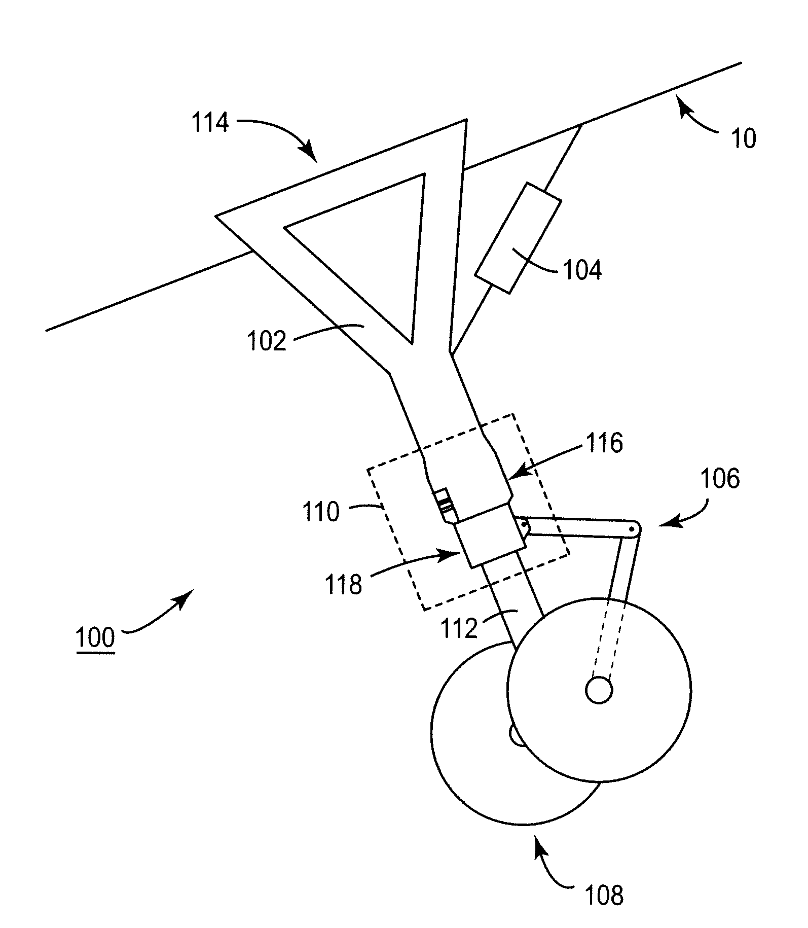
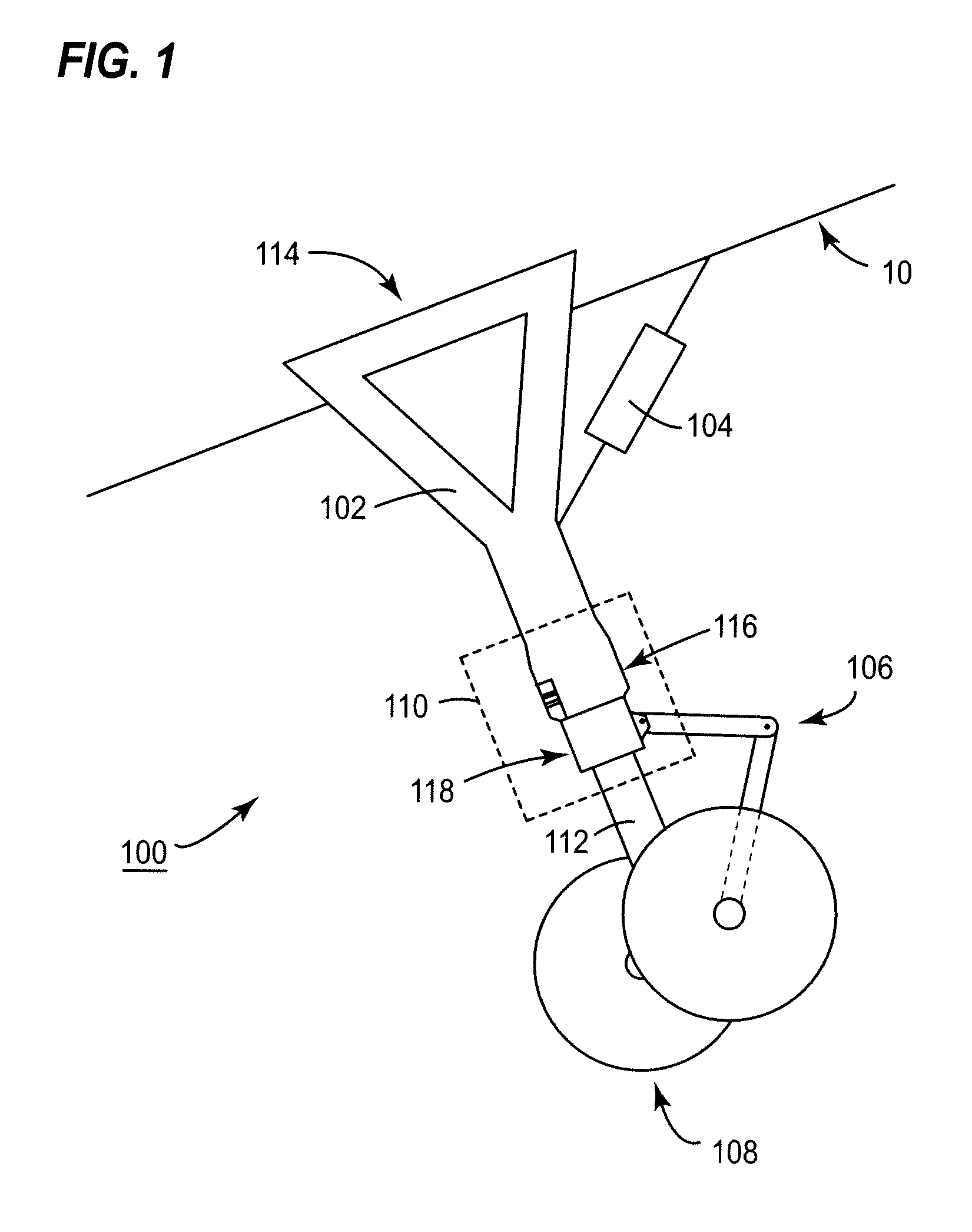
[0022]FIG. 1 shows schematically a diagram of aircraft landing gear 100 according to an embodiment of the present invention. The aircraft landing gear 100 is retractable into a landing gear bay (not shown) provided in the fuselage 10 of an aircraft. A retraction / extension mechanism 104 is provided to move the landing gear 100 into and out of the landing gear bay.

[0023]The landing gear 100 comprises a landing gear yoke 102 that is pivotally mounted at a first end 114 within the landing gear bay. The landing gear 100 also comprises a wheel train unit 108 connected to a shock absorbing oleo 112 and a torque link 106. The oleo 112 and the torque link 106 are connected to a leg portion 116 provided at a second end of the landing gear yoke 102, distal the first end 114 thereof, via a landing gear steering system 110.

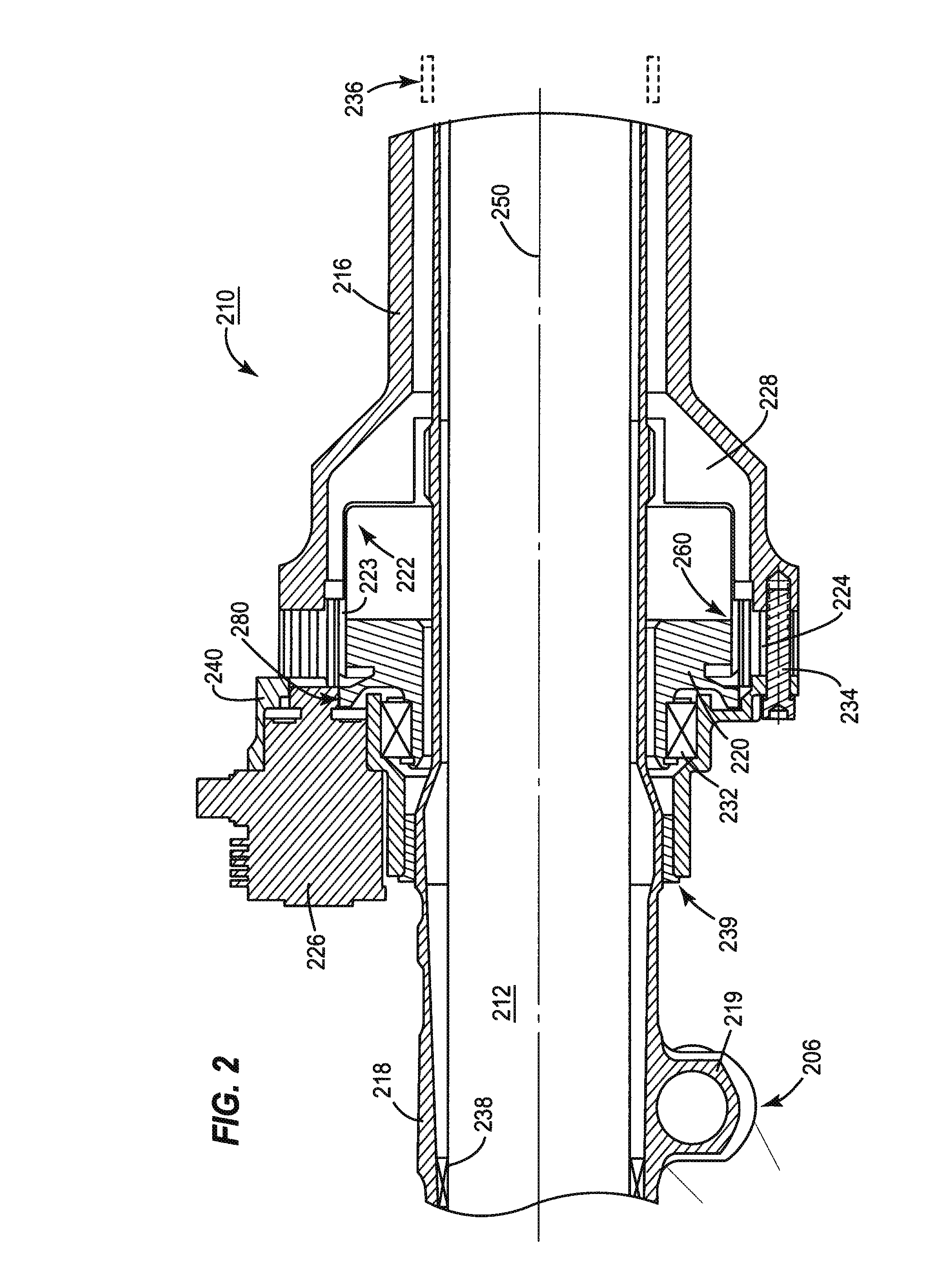
[0024]The landing gear steering system 110 comprises a turning member 118 coupled to an internal harmonic drive mechanism (for examples, see FIGS. 2 and 3, below) that is addi...


PUM


Abstract

An aircraft landing gear steering system comprising a turning member that is operably coupled to a landing gear leg through a harmonic drive mechanism. The landing gear steering system may be electrically driven. Additionally, the landing gear system has various advantages, including the provision of a safe failure mode should the harmonic drive mechanism fail.

Description

CROSS-REFERENCE TO RELATED APPLICATIONS[0001]This application claims priority under 35 U.S.C. §119(a)-(d) or (f) to prior-filed, co-pending British patent application serial number 0808087.1, filed on May 2, 2008, which is hereby incorporated by reference in its entirety.STATEMENT REGARDING FEDERALLY SPONSORED RESEARCH OR DEVELOPMENT[0002]Not ApplicableNAMES OF PARTIES TO A JOINT RESEARCH AGREEMENT[0003]Not ApplicableREFERENCE TO A SEQUENCE LISTING, A TABLE, OR COMPUTER PROGRAM LISTING APPENDIX SUBMITTED ON COMPACT DISC[0004]Not ApplicableBACKGROUND OF THE INVENTION[0005]1. Field of the Invention[0006]The field of the invention relates generally to aircraft landing gear, and more particularly to improved aircraft landing gear steering systems.[0007]2. Description of Related Art[0008]Most aircraft, and particularly those that are heavier than air, are provided with some type of landing gear. Often such landing gear takes the form of one or more sets of freely rotateable wheels provid...

Claims


Application Information

Patent Timeline
IPC IPC(8): B64C25/50F16H35/00
CPCY10T74/19B64C25/505B62D3/02B64C25/50F16H49/001
Inventor HUMPHREY, RICHARD
Owner TRIUMPH ACTUATION SYST UK
Why Eureka
Try Eureka