Method of Reducing Drag and Increasing Lift Due to Flow of a Fluid Over Solid Objects

a fluid flow and flow technology, applied in the direction of airflow influencers, roofs, transportation and packaging, etc., can solve the problems of generating additional drag due to lift generation, exacerbate pressure losses in regions, and objects such as wings, so as to reduce drag, reduce friction drag, and increase lift

Inactive Publication Date: 2009-12-03
SINHATECH (US)
View PDF4 Cites 27 Cited by
  • Summary
  • Abstract
  • Description
  • Claims
  • Application Information

AI Technical Summary

Benefits of technology

[0011]A method of adding a system of small viscous sublayer scale (around 30-80 micron height) backward and/or forward facing steps on the surface of an airfoil or other 2-D or 3-D streamlined aerodynamic body is disclosed, where the backward facing step is in a favorable pressure gradient and forward facing step is in an adverse pressure gradient, so as to speed up the freestream flow over the front portion of the airfoil or body and reduce skin friction drag by creating a marginally separated thin

Problems solved by technology

Losses through turbulent eddies exacerbate pressure losses in regions of separated flow.
In addition, objects such as wings which are shaped to generate lift by inducing a pressure difference between the upper and lower surfaces also generate additional drag due to lift generation.
This is generally necessary for heat exchange from air streams due to significantly lower heat capacities and thermal conductivities of air compared to water or othe

Method used


Image

  • Method of Reducing Drag and Increasing Lift Due to Flow of a Fluid Over Solid Objects
  • Method of Reducing Drag and Increasing Lift Due to Flow of a Fluid Over Solid Objects
  • Method of Reducing Drag and Increasing Lift Due to Flow of a Fluid Over Solid Objects

Examples


Embodiment Construction

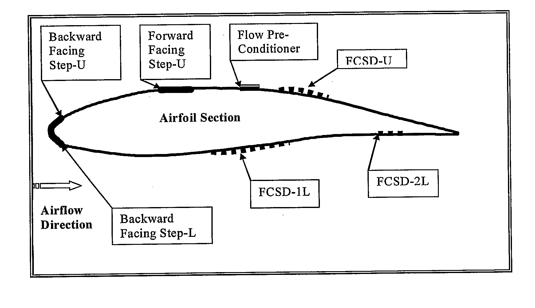
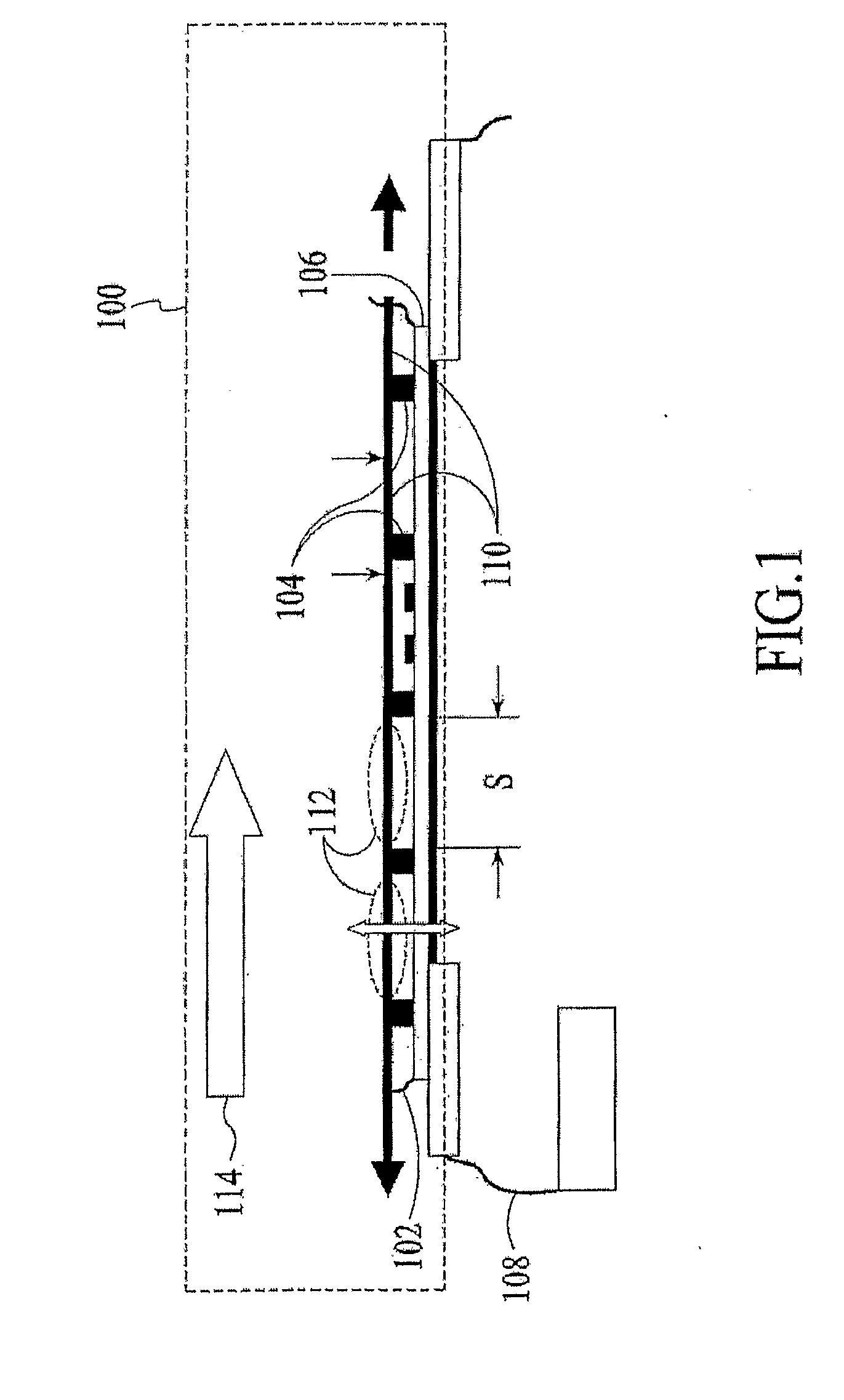
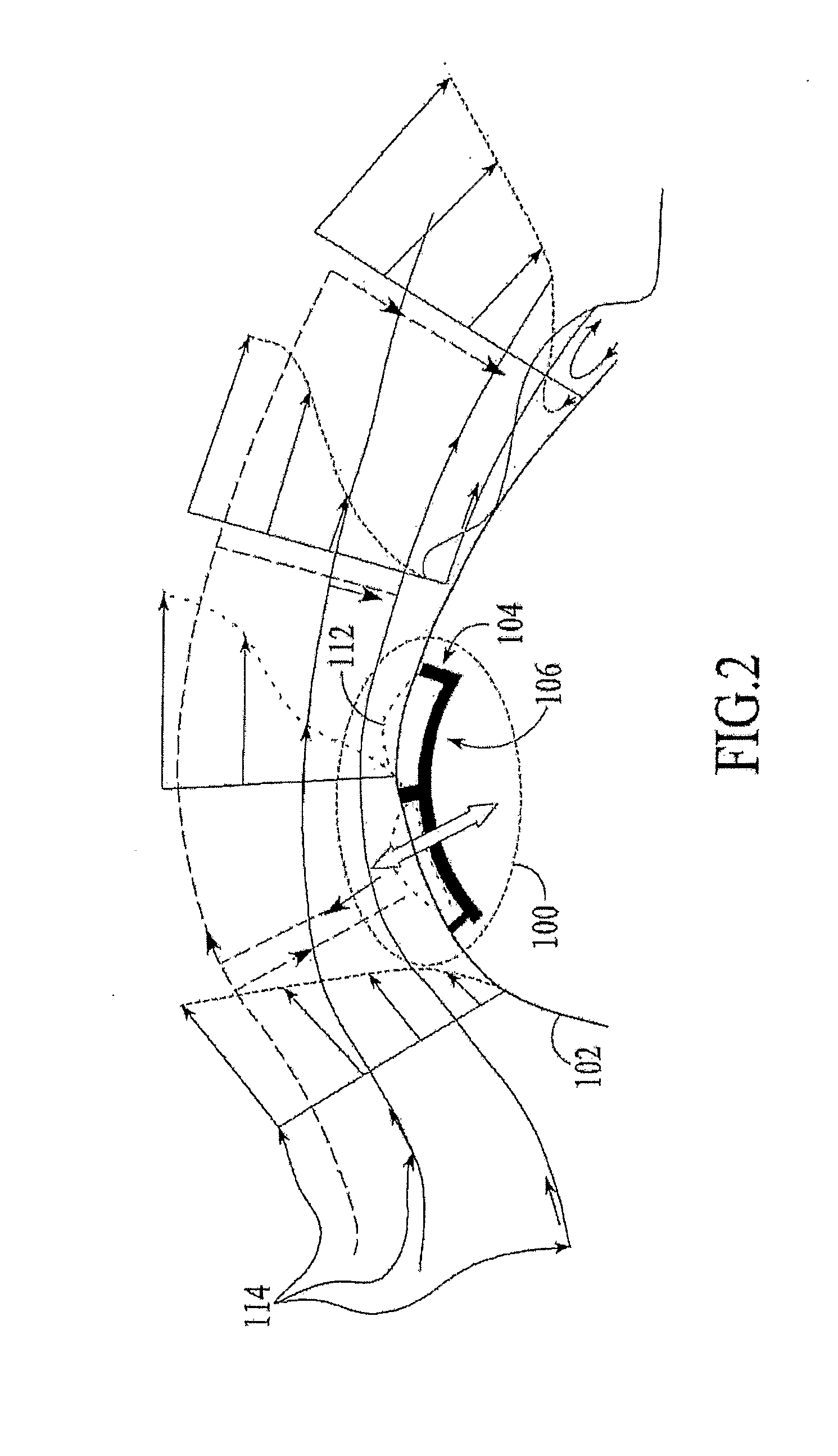
[0046]The present invention relates to the use of devices capable of spectrally altering turbulence to reduce flow induced drag, enhance flow induced lift and enhance flow-surface heat transfer without increasing losses.

[0047]In the last application it is in the field of heat exchangers, and more particularly to a flexible composite surface for enhancing heat transfer in heat exchanger passages while minimizing the drop in flow pressure. The following description is presented to enable one of ordinary skill in the art to make and use the invention and is provided in the context of a patent application and its requirements. Various modifications to the preferred embodiment and the generic principles and features described herein will be readily apparent to those skilled in the art. Thus, the present invention is not intended to be limited to the embodiment shown but is to be accorded the widest scope consistent with the principles and features described herein.

[0048]Generally, a syst...


PUM


Abstract

A method for reducing drag, increasing lift and heat transfer using a de-turbulating device is disclosed, with the preferred form of the deturbulator being a flexible composite sheet. The flexible composite sheet comprising a membrane, a substrate coupled to the membrane, and a plurality of ridges coupled between the membrane and the substrate, wherein a vibratory motion is induced from the flow to at least one segment of a membrane spanning a distances, wherein the vibratory motion is reflected from at least one segment of the membrane to the flow, and; wherein a reduction in fluctuations is caused in the flow pressure gradient and freestream velocity U at all frequencies except around f, where f>>U/s. hi one embodiment, the flexible composite sheet can be wrapped around a blunt leading edge of a plate facing an incoming flow of fluid, hi another embodiment, the flexible composite sheet can also be wrapped around one or more regions of an aerodynamic surface where a flow pressure gradient changes from favorable to adverse, hi another embodiment, the flexible composite sheet is replaced with a plurality of plates coupled to a substrate, wherein the plurality of plates has edges that interact with a fluid flow similar to a compliant surface. A method of adding a system of small viscous sublayer scale (around 30-80 micron height) backward and/or forward facing steps on the surface of an airfoil or other 2-D or 3-D streamlined aerodynamic body is disclosed, where the backward facing step is in a favorable pressure gradient and forward facing step is in an adverse pressure gradient, so as to speed up the freestream flow over the front portion of the airfoil or body and reduce skin friction drag by creating a marginally separated thin (0.1 to 10 microns) slip layer next to the wall behind the backward facing step and extending a significant distance behind said step. This method reduces the drag and increases lift if the body is a wing. Also the same method can be applied to a bluff body, such as an automobile to reduce flow separation induced drag by stabilizing the wake flow and making it appear to the flow as a solid streamiling extension of the original body. The gas mileage of a vehicle improves when treated in this manner.

Description

[0001]The invention described herein was supported by a grant from the United States Government having NASA Contract No. NNL04AA32C and NSF Grant No. 0420115. The United States Government has certain rights in this invention.FIELD OF THE INVENTION[0002]The present invention relates to a method for using turbulence modifying flow-control devices to reduce drag on streamlined and bluff bodies, increase lift generated by lifting bodies and also increase convective heat transfer between a body and the flow without increasing flow losses.BACKGROUND OF THE INVENTION[0003]Reduction of undesirable flow induced drag is important for enhancing the efficiencies of aircraft, automobiles and boats. Additionally, lifting surfaces such as wings also need to maximize lift generation while reducing drag so as to maximize the lift to drag ratio and minimize the size of the wing. Designers usually streamline objects as far as practical to reduce flow induced drag. For subsonic gas flows the primary dr...

Claims


Application Information

Patent Timeline
IPC IPC(8): B64C21/10B62D39/00
CPCB61D17/02B62D35/00B64C21/08B64C21/10B64C2230/06F15D1/12Y02T30/32Y02T50/166B64C23/005Y02T30/00Y02T50/10
Inventor SINHA, SUMON K.SINHA, SUMONTRO
Owner SINHATECH (US)
Why Eureka
Try Eureka