Luminescence Microscopy with Enhanced Resolution

a luminescence microscopy and luminescence enhancement technology, applied in the field of luminescence microscopy with enhanced resolution, can solve the problem that the simultaneous occupation of the triplet state no longer necessarily has negative, and achieve the effects of simple construction, and reducing the number of radiation sources

Inactive Publication Date: 2009-12-03
CARL ZEISS MIKROLMAGING
View PDF8 Cites 12 Cited by
  • Summary
  • Abstract
  • Description
  • Claims
  • Application Information

AI Technical Summary

Benefits of technology

[0021]A substantial advantage of the invention is the flexibility in the choice of dye. While the intersystem crossing required in GSD is limiting, the STED method requires molecules which allow the most efficient possible de-excitation of the S1,0 state. By contrast, the invention makes it possible to use almost any dye whose level diagram corresponds approximately to that shown in FIG. 1. Optimization of the reaction rates (e.g., with respect to moderately longer fluorescence lifetimes) is advantageous, but does not present a fundamental limitation of the method. It must be emphasized that the essential modification with respect to conventional techniques is to be found more in the type of excitation and detection than in the choice of the sample to be examined (in stark contrast to DE 10325460 A1, for example).
[0022]In the STED experiments realized up to the present, two wavelengths are required, whereas the invention works with only one wavelength. It is not necessary to use a plurality of dichroic beamsplitters. Accordingly, a relatively simple construction can be used.
[0023]In STED experiments, it generally makes sense to use intensive pulsed lasers because the population of the excited state should be decreased in the side laser beam area before fluorescence tales place. In contrast, the invention can work with cw lasers irradiating simultaneously. However, it is advantageous to delay the irradiation by the center laser beam with respect to the side laser beam by approximately 10 ns because an extensive depopulation of the ground state has already taken place by then (see FIG. 7). In some circumstances, it is also possible to realize the modulation in the form of a pulsed laser.
[0024]The modulation-marked fluorescence (MMF) according to the invention makes it possible to improve high-resolution optical imaging to an even greater degree. It presents an alternative to the two single-point methods GSD and STED which are already known. As in these known methods, the method according to the invention also works with at least two laser radiation fields (center laser beam and side laser beam). However, whereas the aim in GSD and STED is to completely suppress the fluorescence in the side laser beam area, in MMF the center sample area and the laterally excited sample area are distinguished, e.g., by modulated center laser beam excitation followed by phase-sensitive detection of the signal of interest, and can therefore be separated. The use of a modulation-frequency-sensitive detection, e.g., by means of lock-in technology, is a central aspect for this purpose. Marked fluorescence in the side laser beam area, i.e., excitation through photons of the center laser radiation field, can be avoided by means of an unbalanced intensity ratio between the laser radiation fields and a saturated depopulation of the ground state. A substantial advantage of MMF over the known methods of GSD and STED is the freedom of choosing the fluorophor and the possibility of operating the center laser and side lasers at the same wavelength.

Problems solved by technology

But simultaneous occupation of the triplet state no longer necessarily has negative results.

Method used


Image

  • Luminescence Microscopy with Enhanced Resolution
  • Luminescence Microscopy with Enhanced Resolution
  • Luminescence Microscopy with Enhanced Resolution

Examples


Embodiment Construction

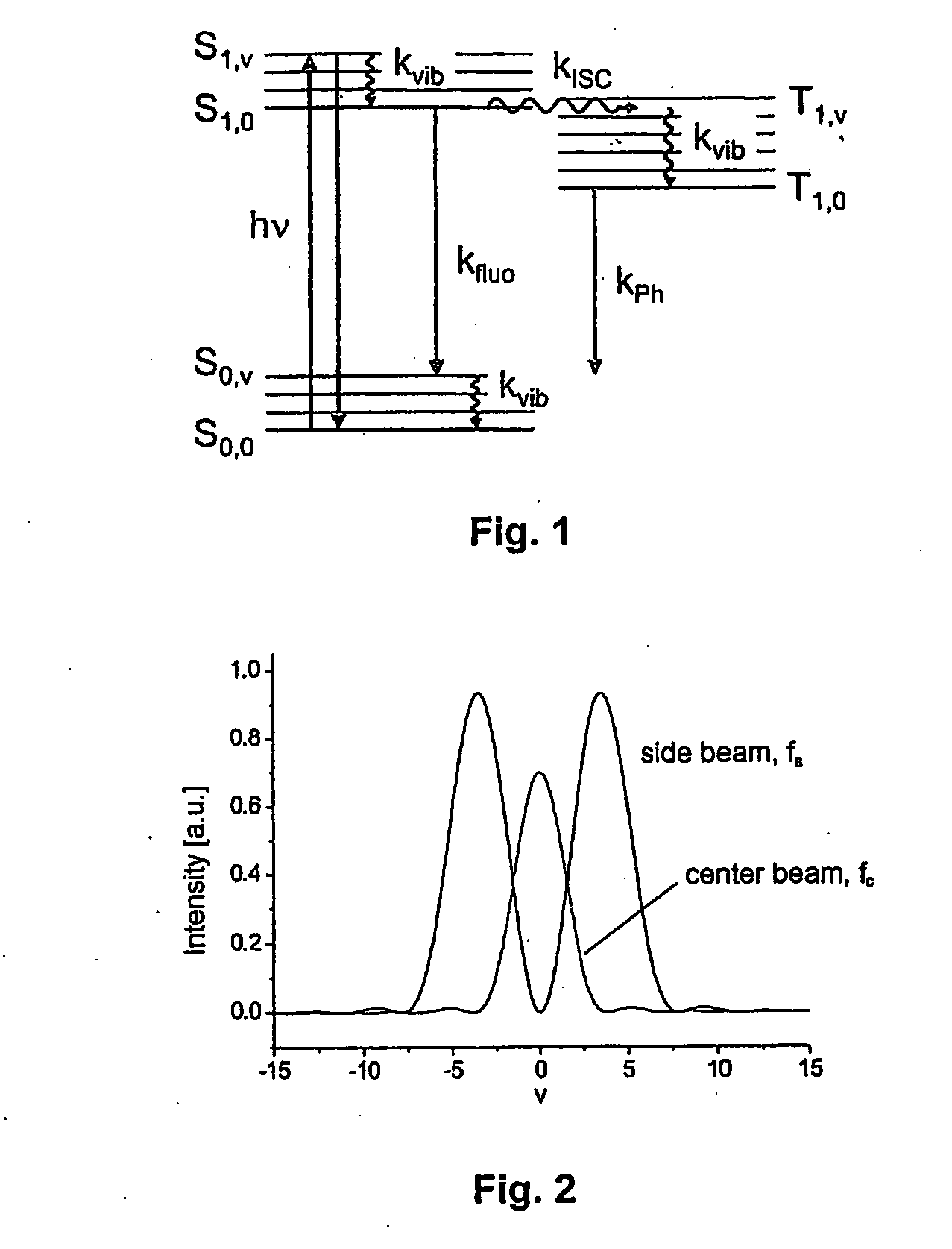
[0034]The typical arrangement, known per se, of the lowest energy level for a fluorescing dye molecule is shown schematically in FIG., 1. Usually photons of energy hv excite the molecules from state S0,0 (approximate vibrational ground state in the lowest electronic state) to a vibration-excited vibronic state S1,v. Conversely, stimulated emission is, of course, also possible. Starting from S1,v, a fast vibrational relaxation takes place in state S1,0 and subsequently, as competing processes, either fluorescence or the transition to the triplet state Ti,v with subsequent phosphorescence.

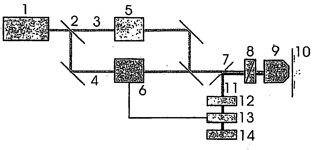
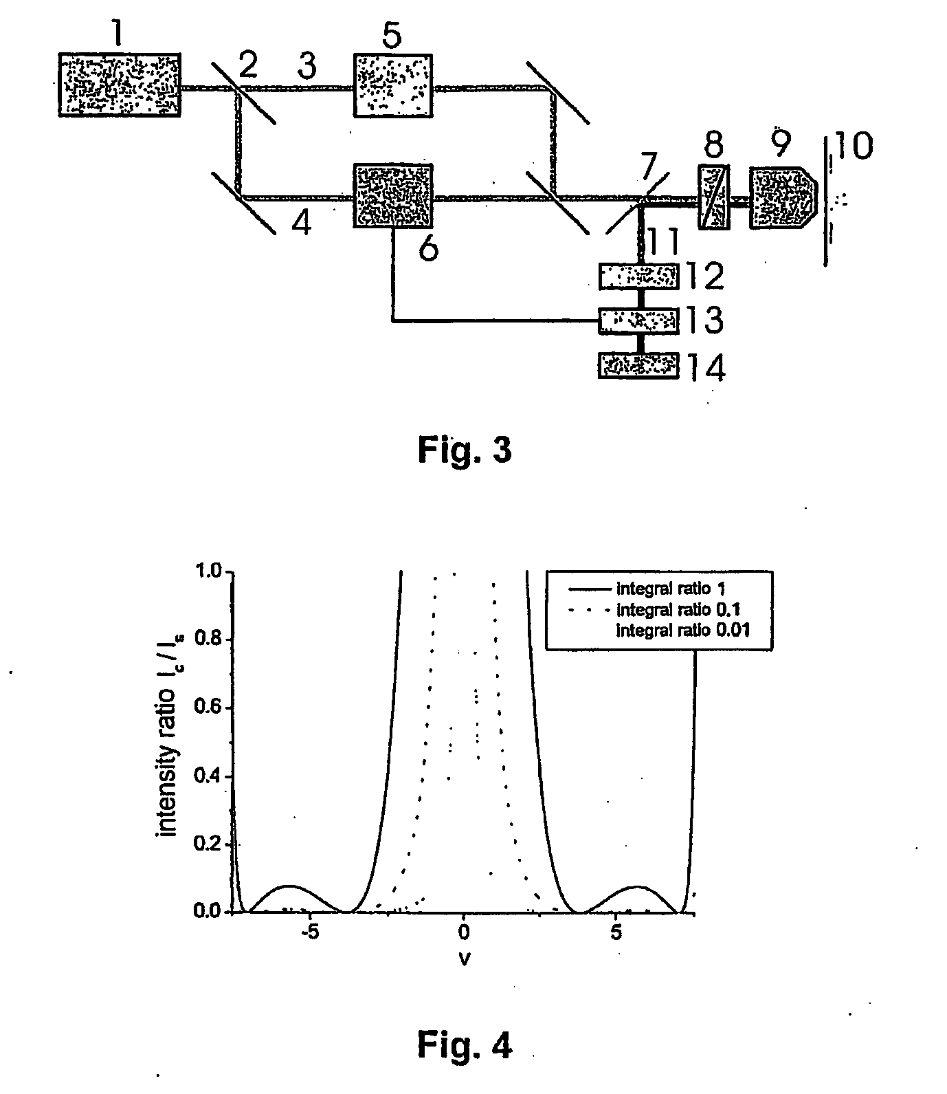
[0035]The excitation is carried out, according to the invention, by at least two different light fields which are arranged in the same way as the excitation laser radiation field and the saturation laser radiation field in the known GSD or STED method. The use of lasers seems sensible but generally does not represent a limitation of the method.

[0036]FIG. 2 shows possible Airy intensity distributions ...


PUM

PropertyMeasurementUnit
frequencyaaaaaaaaaa
frequencyaaaaaaaaaa
frequencyaaaaaaaaaa

Abstract

The invention is directed to a resolution-enhanced luminescence microscopy method in which a sample is excited to the emission of luminescence radiation through irradiation by excitation radiation, and an image of the luminescing sample is acquired. A first partial volume of the sample is irradiated by a first laser radiation field of the excitation radiation, and a second partial volume of the sample is irradiated by a second laser radiation field of the excitation radiation. The first partial volume of the sample and the second partial volume of the sample overlap one another partially but not completely. Only the first laser radiation field is modulated with a first frequency, and luminescence radiation is detected from the first partial volume of the sample with modulation filtering so that luminescence radiation from the second partial volume of the sample is suppressed.

Description

RELATED APPLICATIONS[0001]The present application is a U.S. National Stage application of International PCT Application No. PCT / EP2007 / 007882 filed on Sep. 10, 2007, which claims benefit of German Application No. DE 10 2006 046 369.2 filed on Sep. 29, 2006, the contents of each are incorporated by reference in their entirety.FIELD OF THE INVENTION[0002]The invention is directed to resolution-enhanced luminescence microscopy and particularly to a method in which a luminescing sample to be examined is illuminated by excitation radiation and an image of the sample that has been excited to luminescence is obtained. The invention is further directed to a microscope for resolution-enhanced luminescence microscopy of a sample, means for exciting luminescence which irradiate the sample with excitation radiation, and means for acquiring an image of the excited sample.BACKGROUND OF THE INVENTION[0003]Luminescence microscopy is a typical field of application of light microscopy for examining b...

Claims


Application Information

Patent Timeline
Patent Type & Authority Applications(United States)
IPC IPC(8): G01N21/64G01J1/58
CPCG01N21/6458G02B21/0084G02B21/0076
Inventor LIPPERT, HELMUT
Owner CARL ZEISS MIKROLMAGING
Why Eureka
Try Eureka