
Display device, drive method therefor, and electronic apparatus

a display device and drive method technology, applied in the field of display devices, display methods therefor, and electronic devices, can solve the problems of reducing the color purity of the image portion, difficult to reproduce correct color, and difficulty in sufficiently reducing the amount of color breakage, so as to achieve the effect of increasing the correlation between the field

Inactive Publication Date: 2009-12-03
SONY CORP
View PDF6 Cites 34 Cited by
  • Summary
  • Abstract
  • Description
  • Claims
  • Application Information

AI Technical Summary

Benefits of technology

[0017]In the related art disclosed in Japanese Unexamined Patent Application Publication No. 2002-318564, since the frequency between W and W is one fourth of the field frequency, the effect of preventing color breakup is small. When simultaneous lighting in each field is performed as in the related art disclosed in Japanese Unexamined Patent Application Publication No. 2008-020758, the color purity decreases.
[0019]In order to prevent color breakup without use of a color filter, a variety of techniques for reducing the amount of color breakup by performing various types of processing along the time axis are also being studied, since in-space modulation is considered to be impossible. However, since field-sequential images that are completely separated into R, G, and B have no inter-field relationship in colors therebetween, color breakup occurs under the current situation. Thus, only available methods found effective as measures to prevent color breakup are a method for mixing white while sacrificing color purity and a method for compensating for the low inter-frame correlations by increasing the field frequency, for example, by interposing a white frame with an increased field frequency.
[0020]Accordingly, it is desired to provide a display device that is capable of preventing occurrence of color breakup in the field sequential system, a drive method for the display device, and an electronic apparatus including the display device.
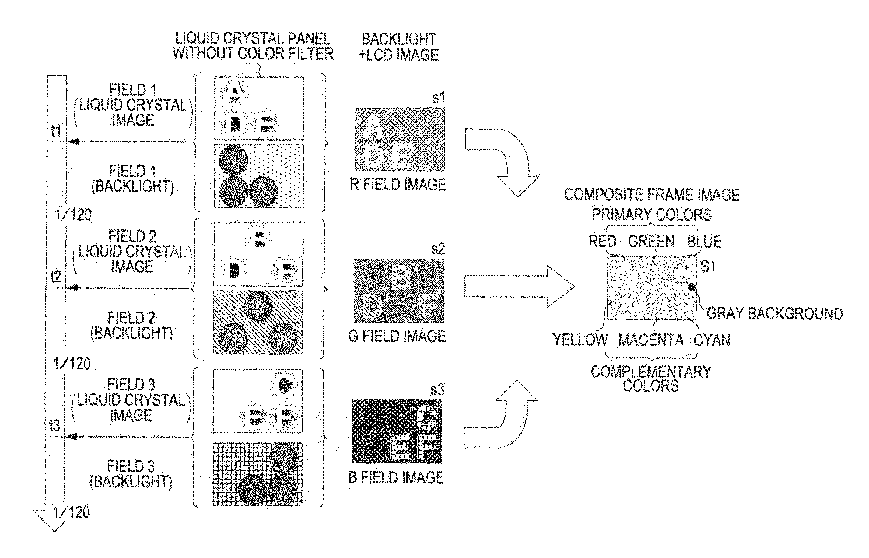
[0022]Rather than expressing all colors with, for example, the three primary colors, the display device having the above-described configuration employs a scheme for allocating the white components or complementary-color components of the color, determined by the mixing ratio of the illumination lights, to the fields. With this arrangement, color combination is performed in a space and the combination of the amounts of illumination (the amounts of lighting) is performed over time. As a result, the inter-field correlation is increased compared to a case in which this scheme is not employed. An increase in the inter-field correlation can prevent occurrence of color breakup in the field sequential system.
[0023]According to the present invention, colors are spatially mixed and the amounts of illumination are temporally combined. Thus, even with a field-sequential display configuration without a color filter, it is possible to achieve color display with almost no color breakup.

Problems solved by technology

The related art disclosed in Japanese Unexamined Patent Application Publication No. 2008-020758 has a drawback in that, when a display image portion with high color purity exists on a display screen, white light is mixed thereinto to reduce the color purity of the image portion, thus making it difficult to reproduce correct color.
With this frequency, it is difficult to sufficiently reduce the amount of color-breakup.
With the frequency, however, it is difficult to reduce the amount of color breakup to the visually perceivable level or less.

Method used


Image

  • Display device, drive method therefor, and electronic apparatus
  • Display device, drive method therefor, and electronic apparatus
  • Display device, drive method therefor, and electronic apparatus

Examples


example

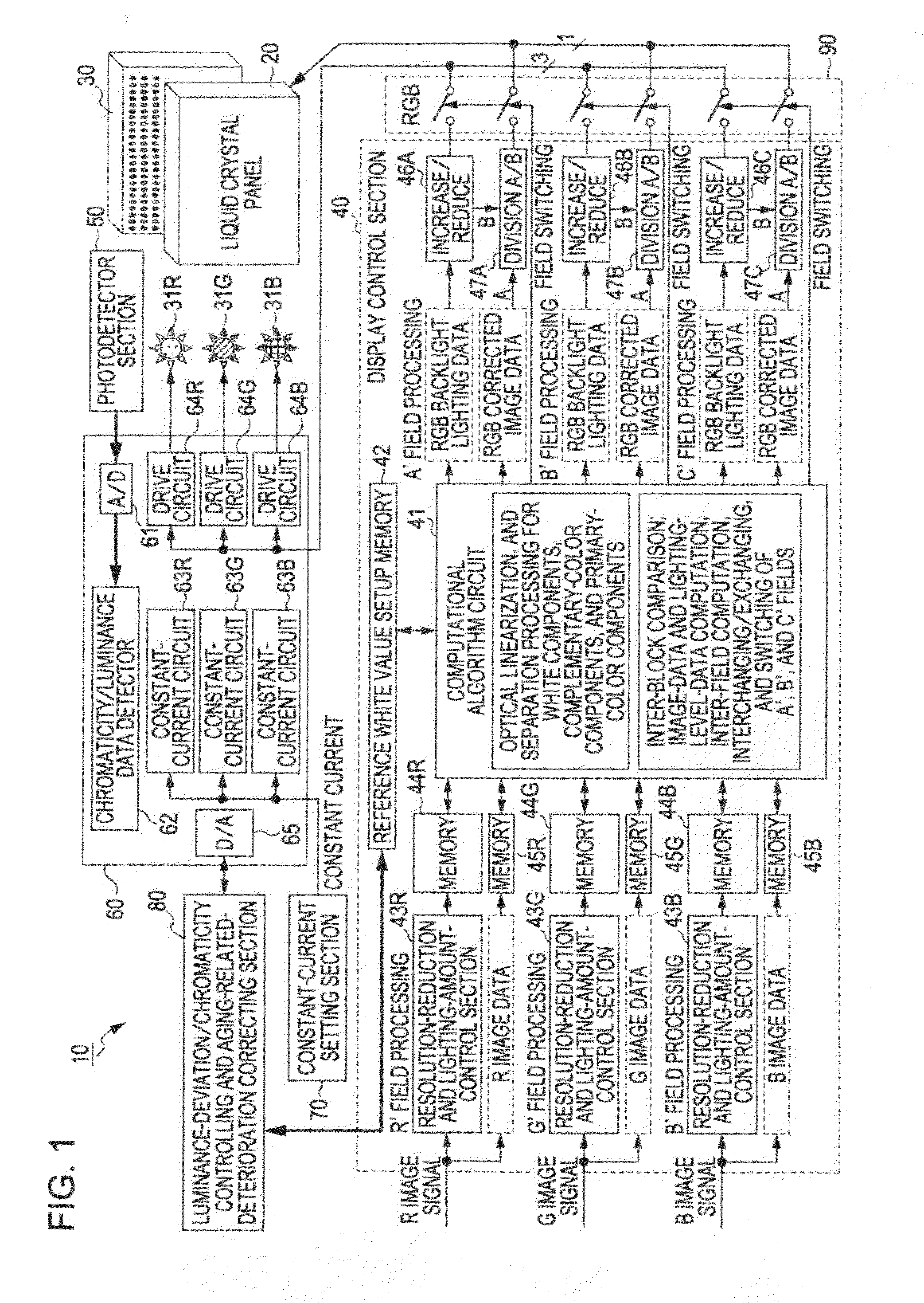
[0205]A specific example for embodying the above-described concepts of the present invention will be described next. Drive control for the liquid crystal panel 20 and the light source section (backlight) 30 according to this example is executed under the control of the display control section 40, particularly, the computational algorithm circuit 41, shown in FIG. 1.

[0206]The computational algorithm circuit 41 has at least three functions. A first function is to determine the degree of white or the degree of complementary color of the light sources 31 on the basis of the amounts of lighting of individual illumination colors emitted by the light sources 31 and determined by signals of a color image to be displayed. A second function is to set, on the basis of a result of the determination, white components or complementary-color components of a color that is defined by the mixing ratio of multiple illumination colors. A third function is to allocate the set color components or complem...


PUM


Abstract

A display device includes: a light source section having multiple light sources to emit light in illumination colors including three primary colors of light; a display section for displaying an image in monochrome color by modulating the light emitted from the light source section; and a display control section for driving the light source section and the display section in a field sequential system. The display control section includes a determining section for determining a degree of white or a degree of complementary color of the light sources on the basis of an amount of lighting of each of the illumination colors of the light sources, a setting section for setting white components or complementary-color components of a color determined by a mixing ratio of the illumination colors, and an allocating section for allocating the set white components or the complementary-color components to the fields.

Description

[0001]The present application claims priority from Japanese Patent Application No. JP 2008-131665 filed in the Japanese Patent Office on May 20, 2008, the entire content of which is incorporated herein by reference.BACKGROUND OF THE INVENTION[0002]1. Field of the Invention[0003]The present invention relates to display devices, display methods therefor, and electronic apparatuses. In particular, the present invention relates to a display device, a display method therefor, and a display device which display images by utilizing and modulating light of light sources.[0004]2. Description of the Related Art[0005]Color image display system can be broadly divided into two systems according to an additive color mixing method. A first system is additive color mixing based on a spatial color mixing principle. Specifically, sub-pixels of the three primary colors of light, namely, R (red), G (green), and B (blue), are arranged in a plane at a high density, and the individual color lights are mad...

Claims


Application Information

Patent Timeline
IPC IPC(8): G09G5/10G09G3/36
CPCG09G3/2003G09G2360/16G09G3/3426G09G3/3611G09G3/3688G09G2310/0235G09G2310/0248G09G2320/0233G09G2320/0242G09G2320/064G09G2320/0646G09G2320/0666G09G2340/06G09G2360/145G09G3/3413
Inventor FURUKAWA, NORIMASAASANO, MITSUYASUNISHI, TOMOHIRO
Owner SONY CORP
Learn More