MEMS variable capacitor

Inactive Publication Date: 2009-12-03
KK TOSHIBA
View PDF15 Cites 8 Cited by
  • Summary
  • Abstract
  • Description
  • Claims
  • Application Information

AI Technical Summary

Problems solved by technology

Consequently, there is a serious problem that the beam is warped up and down by a small amount of residual stress of materials constituting the beam.
Therefore, it is very difficult to create a capacity value of the variable capacitor before / after voltage application as designed.
Therefore, there is a conflicting problem that materials having a large electrostriction effect is difficult to control the residual strain and materials relatively easy to control the residual strain has a small electrostriction effect.
This is one of the largest problem preventing industrial application of a piezoelectric drive MEMS variable capacitor.
These inventions have almost resolved the warp problem of the piezoelectric actuator, but a portion of the movable electrode is also based on a unimorph structure made of a lower electrode / a piezoelectric film / an upper electrode / a support film similar to the actuator or a bimorph structure made of a lower electrode / a lower piezoelectric film / an upper piezoelectric film / an upper electrode, therefore, there is also a problem that slight residual stress produces a warp on the movable electrode portion and even if the movable electrode contacts the fixed electrode by the piezoelectric actuator, only part of the movable electrode closely contacts and the maximum capacity value is small.
Moreover, there has been a problem that a difference of thermal expansion coefficient between the movable electrode and the substrate produces a difference of dimension between the movable electrode and the substrate, for example, at a high temperature and low temperature, thus a stress of contraction or extension is applied to the movable electrode, the movable electrode is deformed and a contact area between the movable electrode and the fixed electrode is reduced.

Method used


Image

  • MEMS variable capacitor
  • MEMS variable capacitor
  • MEMS variable capacitor

Examples


first embodiment

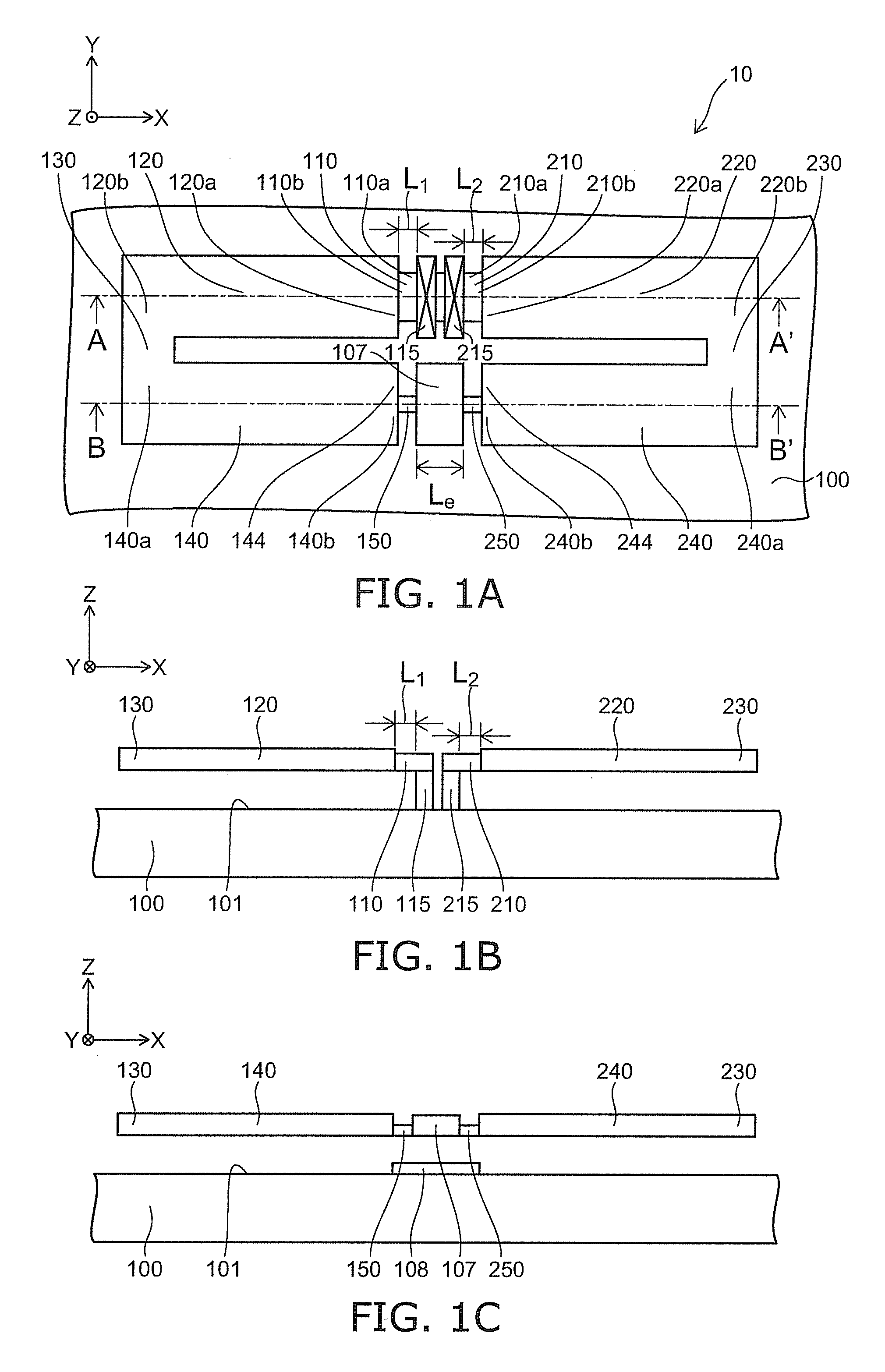
[0048]FIGS. 1A to 1C are schematic views illustrating the configuration of a MEMS variable capacitor according to a first embodiment of the invention.

[0049]That is, FIG. 1A is a schematic plan view, FIG. 1B is a cross-sectional view along A-A′ line of FIG. 1A, FIG. 1C is a cross-sectional view along B-B′ line of FIG. 1A.

[0050]As shown in FIGS. 1A to 1C, a direction perpendicular to a main surface 101 of a substrate 100 is taken to be a Z-axis direction, a direction perpendicular to the Z-axis and parallel to the main surface 101 is taken to be an X-axis direction and a direction perpendicular to the X-axis and the Z-axis is taken to be a Y-axis direction. In the following, a first direction is the X-axis direction and a second direction is the Y-axis direction.

[0051]As shown in FIGS. 1A to 1C, in the MEMS variable capacitor 10 according to the first embodiment of the invention, one end 110a of a first connection beam 110 is a fixed end and fixed to the substrate 100 through a first ...

second embodiment

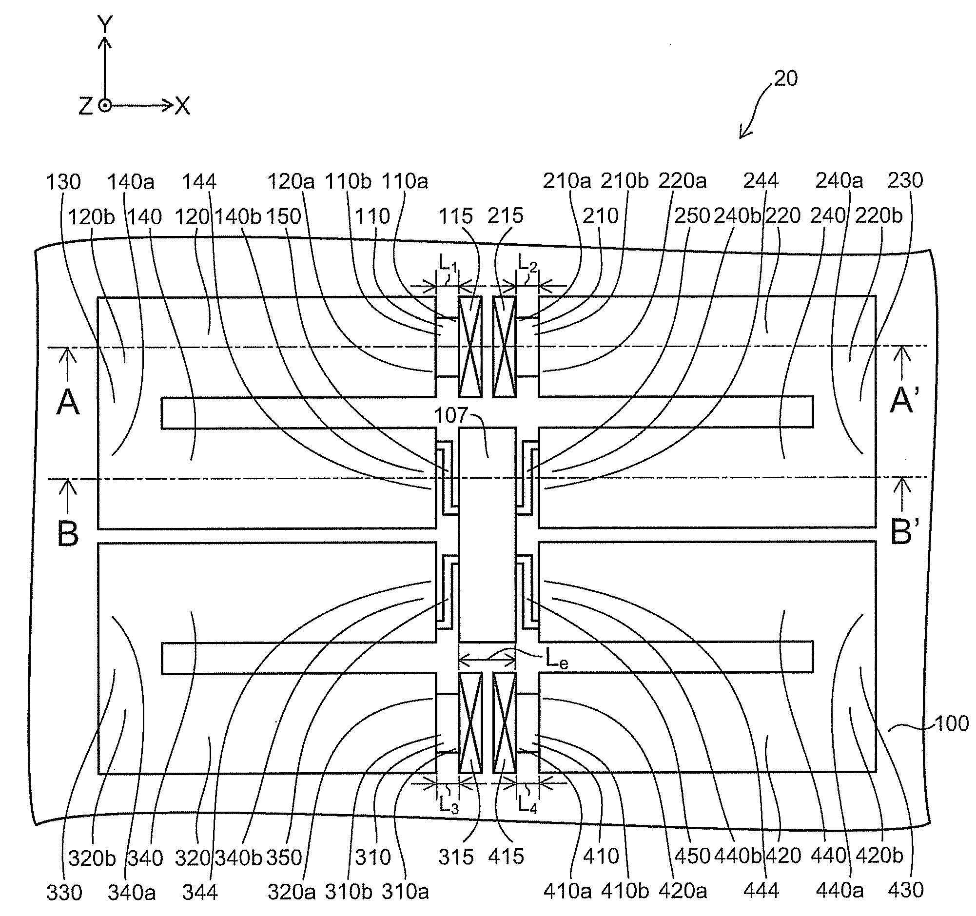
[0093]FIG. 3 is a schematic plan view illustrating the configuration of a MEMS variable capacitor according to a second embodiment of the invention.

[0094]As shown in FIG. 3, the MEMS variable capacitor 20 according to the second embodiment of the invention is a combination of two groups of the MEMS variable capacitor according to the first embodiment.

[0095]In FIG. 3, the first anchor 115, the first connection beam 110, the first actuation beam 120, the first connection portion 130, the second actuation beam 140, the first weak connection beam 150 and the movable electrode 107, and the second anchor 215, the second connection beam 210, the third actuation beam 220, the second connection portion 230, the fourth actuation beam 240, the second weak connection beam 250 and the movable electrode 107 are similar to those of the MEMS variable capacitor 10, and thus the description is omitted.

[0096]The MEMS variable capacitor 20 has further includes the following.

[0097]One end 310a of a thir...

third embodiment

[0147]FIG. 6 is a schematic plan view illustrating the configuration of a MEMS variable capacitor according to a third embodiment of the invention.

[0148]FIG. 7 is a cross-sectional view taken along C-C′ line of FIG. 6.

[0149]As shown in FIG. 6, the MEMS variable capacitor 30 according to the third embodiment is the MEMS variable capacitor including: the first actuation beam 120 having the one end 120a fixed on the substrate 100, the another end served as the first connection end 120b and the piezoelectric film sandwiched between the lower electrode and the upper electrode; the second actuation beam 140 having the one end served as the second connection end 140a connected to the first connection end 120b, extending from the second connection end 140a in the parallel and reverse direction to the first actuation beam 120, and having the another end 140b served as the first action end 144 and the piezoelectric film sandwiched between the lower electrode and the upper electrode; the third...


PUM


Abstract

A MEMS variable capacitor includes: a first connection beam having one end fixed to a substrate; a first actuation beam connected to the first connection beam; a second actuation beam connected to the first actuation beam and extending in a reverse direction; a second connection beam having one end fixed to the substrate; a third actuation beam connected to the second connection beam; a fourth actuation beam connected to the third actuation beam and extending in a reverse direction; a movable electrode provided between the second and fourth actuation beams; and a fixed electrode provided on the substrate opposed to the movable electrode. The first to fourth actuation beams have a piezoelectric film sandwiched between a lower electrode and an upper electrode, the first and third actuation beams are placed on a line, the second and fourth actuation beams are placed on a line, and the first and second actuation beams and the third and fourth actuation beams are placed symmetrically about a line.

Description

CROSS-REFERENCE TO RELATED APPLICATIONS[0001]This application is based upon and claims the benefit of priority from the prior Japanese Patent Application No. 2008-142589, filed on May 30, 2008; the entire contents of which are incorporated herein by reference.BACKGROUND OF THE INVENTION[0002]1. Field of the Invention[0003]This invention relates to a MEMS (Micro-electromechanical System) variable capacitor having a piezoelectric actuation mechanism based on a piezoelectric thin film.[0004]2. Background Art[0005]In recent years, a variable capacitor and a switch based on an actuator fabricated by MEMS technique have been receiving attention. That is, a movable electrode is formed on a beam supported in air above a substrate, a fixed electrode is formed on a facing substrate, and then the variable capacitor and the switch are constituted so that actuating the beam by an electrostatic force, a thermal stress, an electromagnetic force and a piezoelectric force varies a distance between t...

Claims


Application Information

Patent Timeline
IPC IPC(8): H01G5/16
CPCH01G5/16H01H2057/006H01G5/18
Inventor KAWAKUBO, TAKASHINAGANO, TOSHIHIKONISHIGAKI, MICHIHIKOITAYA, KAZUHIKO
Owner KK TOSHIBA
Why Eureka
Try Eureka