Method of reconstructing an image function from radon data

a radon and image function technology, applied in the field of reconstructing an image function from radon data, can solve the problems of inability to avoid disadvantages, errors and artifacts which have a tendency to increase, and iteration leads to extremely long calculation times, so as to improve imaging resolution and increase the range of applications

Inactive Publication Date: 2009-12-03
UNIVERSITY OF OREGON +1
View PDF8 Cites 37 Cited by
  • Summary
  • Abstract
  • Description
  • Claims
  • Application Information

AI Technical Summary

Benefits of technology

[0010]The objective of the invention is to provide an improved method of reconstructing image functions from Radon data, avoiding the drawbacks of the above reconstructing and imaging techniques and leading to an increased range of applications in non-destructive investigations. In particular, the objective of the invention is to provide a reconstructing method yielding image functions with improved imaging resolution even with a limited number of views for irradiating an object

Problems solved by technology

The essential disadvantage of the iterative reconstruction of higher resolution images is that the iteration leads to extremely long calculation times. The filtered back-projection method relies in principle on the Fourier-slice theorem describing a relationship between the Fourier transform of the Radon data and Fourier transformed image data.
A general disadvantage of using the Fourier-slice theorem lies in the fact that an interpolation step in the reconstruction results in errors and artifacts which have a tendency to increase with increasing space frequency.
This disadvantage can only be avoided by using detectors with high resolution.
However, the application of these detectors is limited in terms of dose burden, costs and data processing time.
However, the improvement of the imaging resolution can be limited by the number of views.
As the number of views is restricted with a typical computer tomography device to about 1.000 per full circle, an i

Method used


Image

  • Method of reconstructing an image function from radon data
  • Method of reconstructing an image function from radon data
  • Method of reconstructing an image function from radon data

Examples


Embodiment Construction

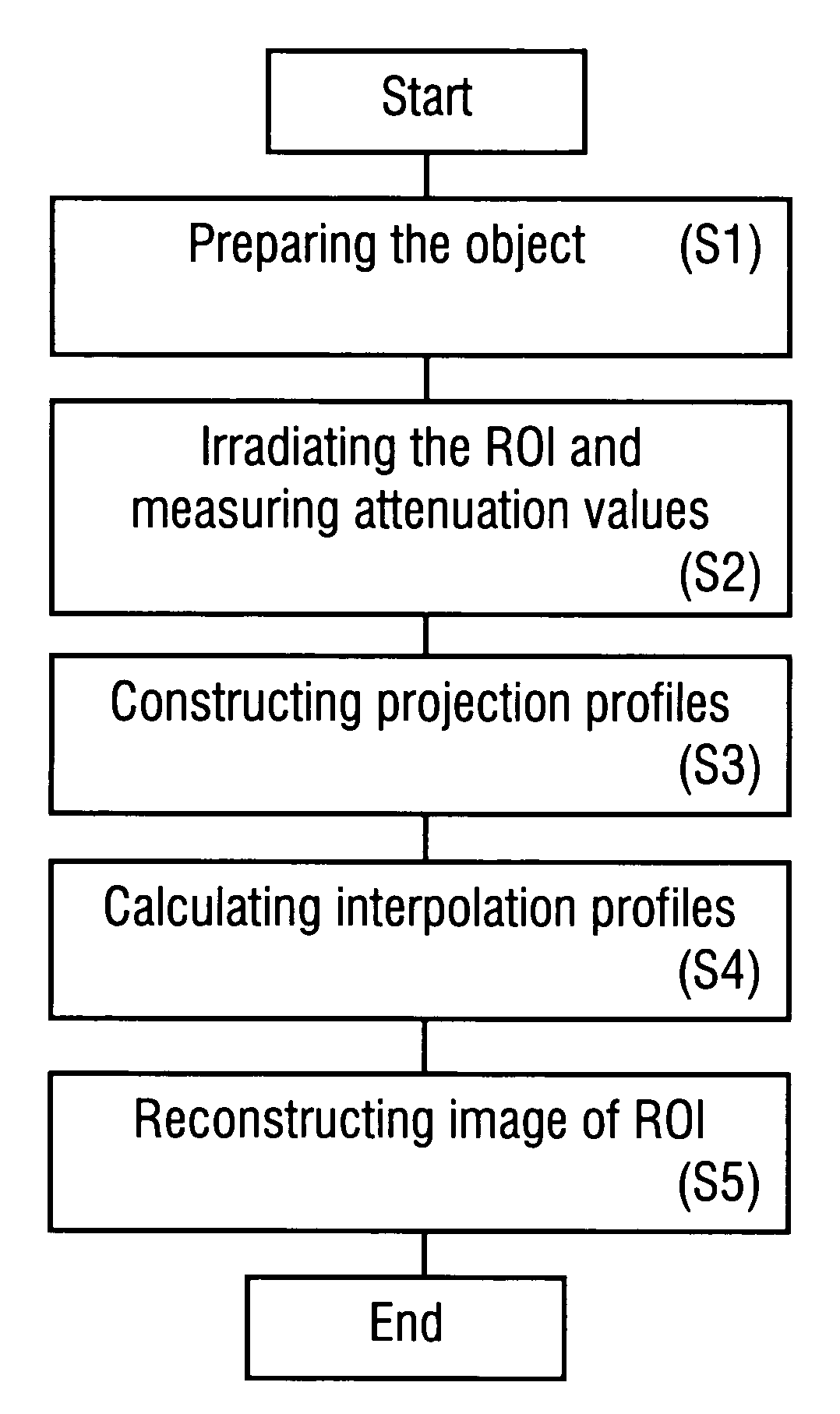
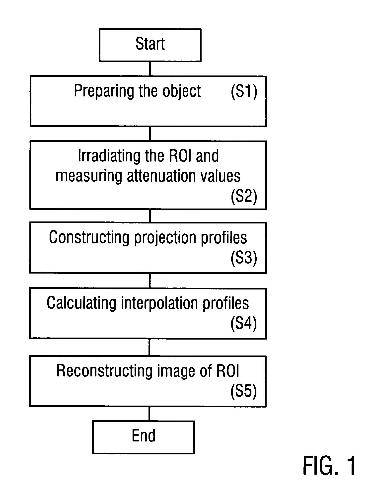
[0033]The invention is described in the following with reference to the preferred application in computer tomography. It is emphasized that the invention can be implemented in an analogous way with the application of other types of energy input beams (like e.g. neutrons or light, e.g. in the VIS or IR range). Furthermore, the following description of the preferred embodiments mainly refers to the principles of constructing interpolation profiles, including data collection and data processing. Details of the structure and operation of CT devices used for implementing the invention are not described as long as they are known from conventional CT devices.

[0034]Furthermore, the invention is described in the following with reference to the preferred application of the OPED algorithm. The description of the OPED algorithm for image construction as described in EP 04031043.5 is introduced into the present specification by reference. If the image function is calculated using the conventiona...


PUM


Abstract

A method of reconstructing an image function on the basis of a plurality of projection profiles corresponding to a plurality of projection directions through a region of investigation, each projection profile including a series of value positions, wherein measured projection values corresponding to projection lines parallel to the respective projection direction are assigned to respective value positions and a plurality of remaining value positions are empty, comprises the steps of (a) assigning first interpolation values to the empty value positions for constructing a plurality of interpolation profiles on the basis of the projection profiles, wherein the first interpolation values are obtained from a first interpolation within a group of measured projection values having the same value position in different projection profiles, and (b) determining the image function by applying a predetermined reconstruction algorithm on the interpolation profiles.

Description

TECHNICAL FIELD[0001]The present invention relates to a method of reconstructing an image function from Radon data comprising a plurality of projection functions measured corresponding to a plurality of predetermined projection directions. Furthermore, the present invention relates to a method for imaging a region of investigation on the basis of the above reconstructing method.TECHNICAL BACKGROUND[0002]The non-destructive investigation of samples is an important objective in various technical fields like material sciences, non-destructive testing, medical examinations, archaeology, construction technique, techniques concerning security matters etc. One approach for obtaining an image of a sample e.g. by computer tomography (CT) is based on an irradiation through a sample plane from different projection directions with X-rays, followed by the reconstruction of the sample plane on the basis of attenuation data measured at different directions. The entirety of the measured attenuation...

Claims


Application Information

Patent Timeline
IPC IPC(8): G06K9/00
CPCA61B6/027G06T11/005
Inventor XU, YUANTISCHENKO, OLEGHOESCHEN, CHRISTOPH
Owner UNIVERSITY OF OREGON
Why Eureka
Try Eureka