Systematic disc resonator gyroscope tuning

a disc resonator and gyroscope technology, applied in the field of gyroscopes, can solve the problems large and heavy, and the mechanism of older conventional mechanical gyroscopes is very heavy, and achieves the effects of large and heavy, high cost, and high accuracy

Active Publication Date: 2009-12-10
THE BOEING CO
View PDF3 Cites 24 Cited by
  • Summary
  • Abstract
  • Description
  • Claims
  • Application Information

AI Technical Summary

Problems solved by technology

Older conventional mechanical gyroscopes were very heavy mechanisms by current standards, employing relatively large spinning masses.
Currently this is often performed with expensive conventional spinning mass gyros (e.g., a Kearfott inertial reference unit) or conventionally-machined vibratory gyroscopes (e.g. a Litton hemispherical resonator gyroscope inertial reference unit).
However, both of these are very expensive, large and heavy.
This transfer or coupling admits external disturbances and energy loss indistinguishable from inertial rate input and hence leads to sensing errors and drift.
Other planar tuning fork gyroscopes may achieve a degree of isolation of the vibration from the baseplate, however these gyroscopes lack the vibrational symmetry desirable for tuned operation.
However, these designs are not suitable for or have significant limitations with thin planar silicon microfabrication.
However its high aspect ratio and 3D curved geometry is unsuitable for inexpensive thin planar silicon microfabrication.
Moreover, the case for this gyroscope is not of the same material as the resonator proof mass so that the alignment of the pickoffs and torquers relative to the resonator proof mass change with temperature, resulting in gyroscope drift.
Previous tuning techniques for DRGs involved multi-step trial and error or computerized search methods such as simulated annealing, which are laborious or time consuming.

Method used


Image

  • Systematic disc resonator gyroscope tuning
  • Systematic disc resonator gyroscope tuning
  • Systematic disc resonator gyroscope tuning

Examples


Embodiment Construction

[0038]1. Overview

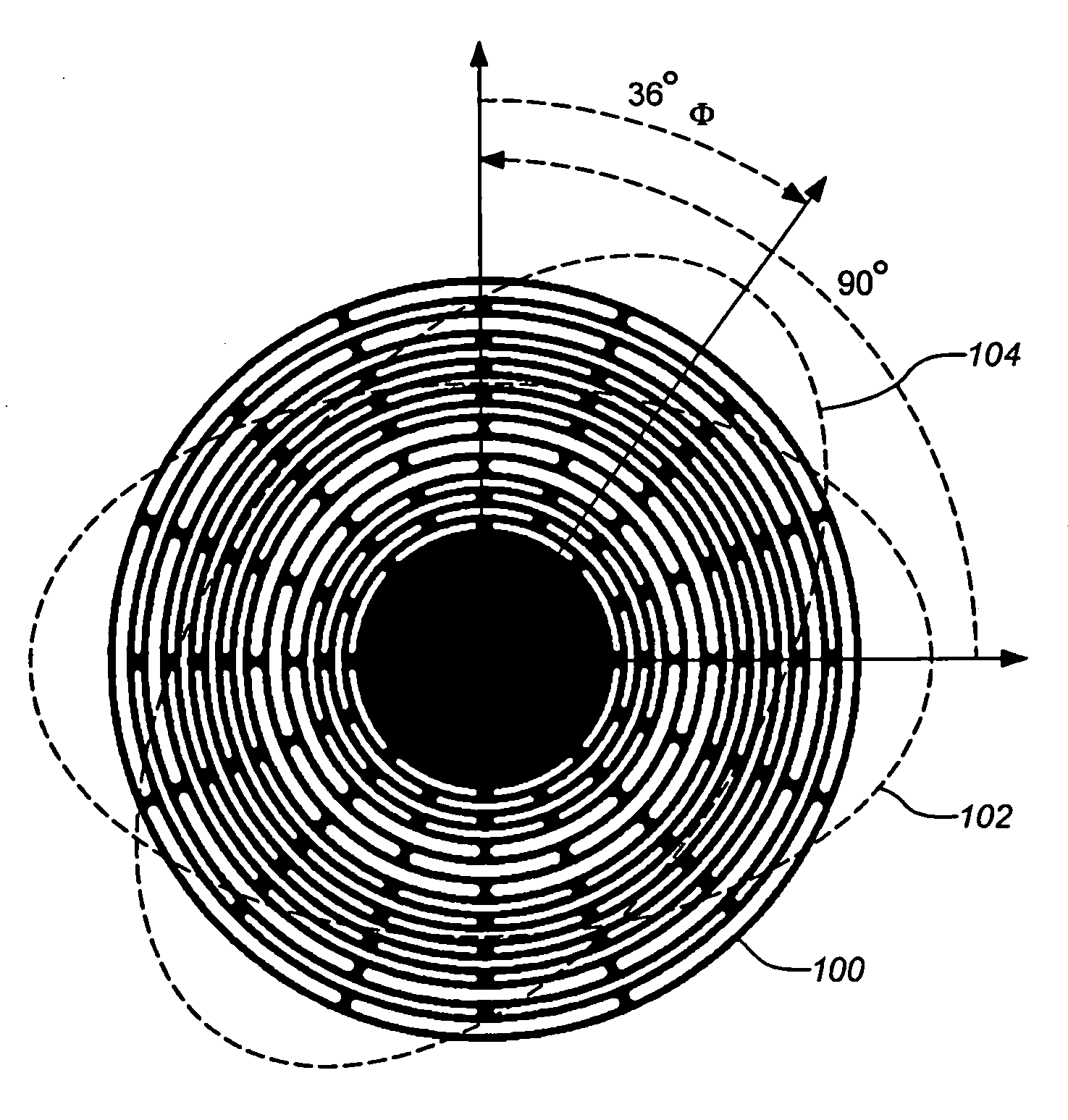
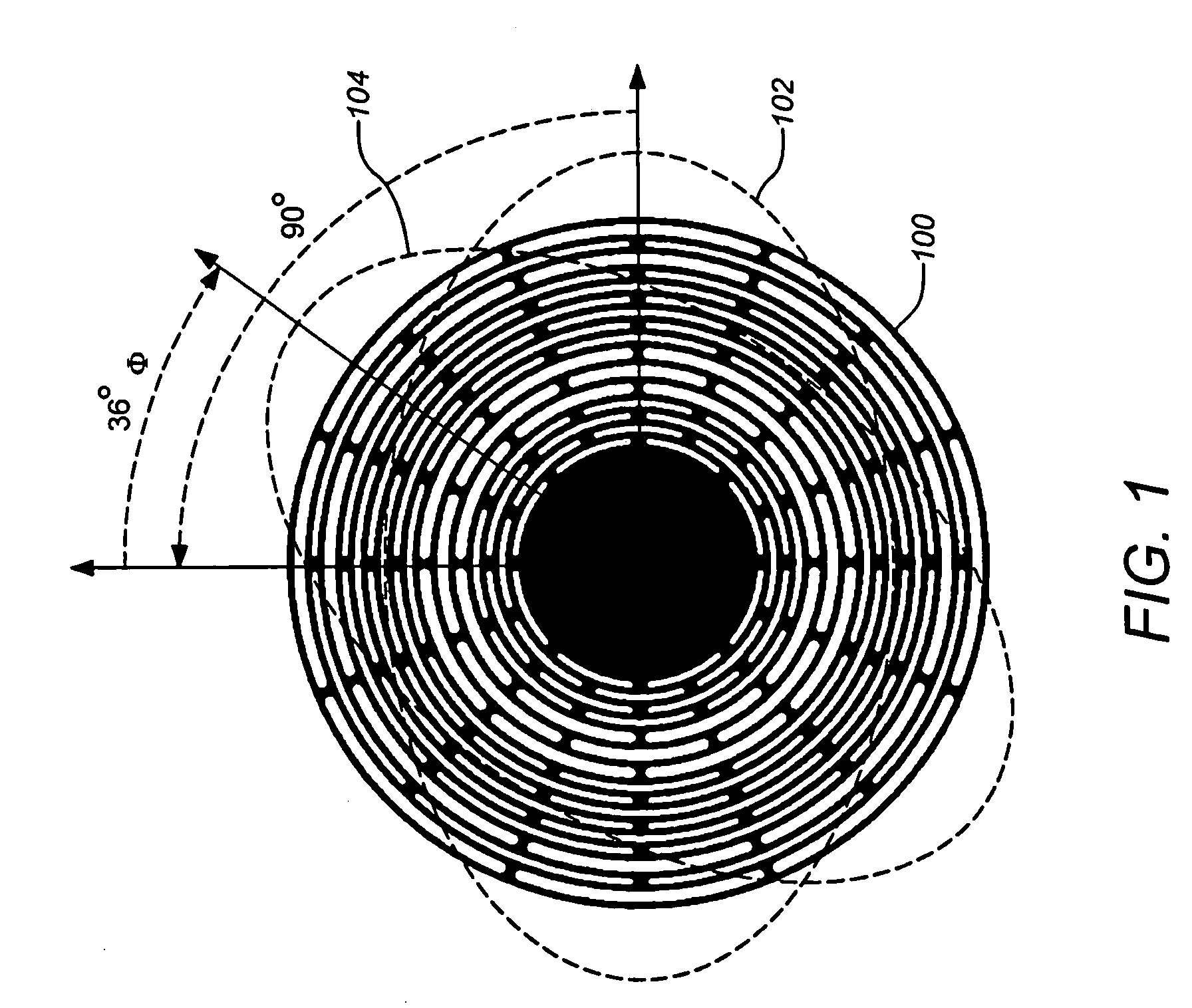
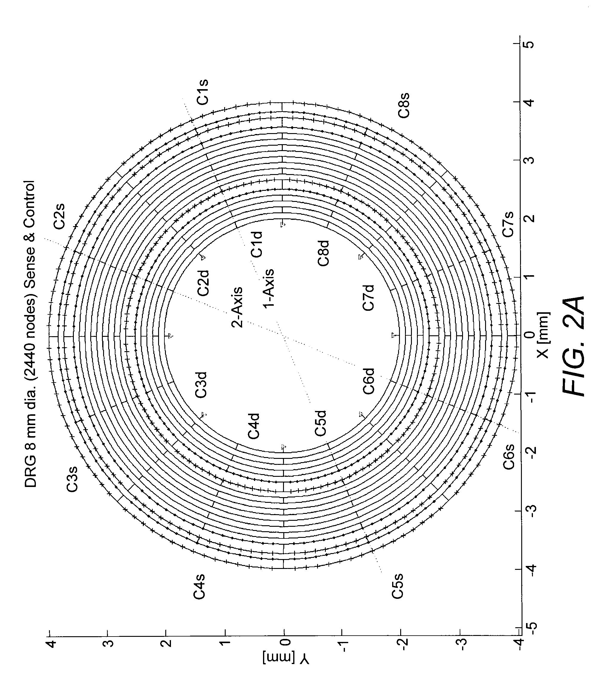
[0039]A systematic method for frequency tuning a disc resonator gyroscope (DRG) in a single step is provided. One or two transfer functions may be analyzed to fully determine the needed sin(4θ) and cos(4θ) asymmetry correction components. One or two of the four groups of four electrostatic bias electrodes or four groups of four laser trimming locations are utilized to correct all the sin(4θ) and cos(4θ) asymmetry components which can give rise to mistuning of the DRG.

[0040]This technique avoids previous laborious or time consuming multi-step trial and error or computerized search methods such as simulated annealing. From the residues of device transfer functions the frequency split, Δf, and orientation, θo, of the Coriolis modes and the fourth Fourier component of asymmetry is systematically determined using relations based on analysis of the finite element model equations. The required cos(4θ) and sin(4θ) asymmetry correction components a4=−Δf cos(4θ0) and b4=−Δf s...


PUM


Abstract

Tuning an axisymmetric resonator such as in a disc resonator gyroscope (DRG) is disclosed. Frequency tuning a DRG in a single step informed by a systematic physical model of the resonator structure, sensing and actuation elements, such as a finite element model, is provided. The sensitivity of selected trimming positions on the resonator to reducing asymmetry terms is determined via perturbations of the systematic model. As well, the dependence of the parameters of model transfer functions between actuation and sensing elements on resonator asymmetry are systematically determined. One or two measured transfer functions may then be analyzed according to the systematic model to fully determine the needed asymmetry correction components of the DRG. One or two of four groups of four electrostatic bias electrodes or four groups of four laser trimming locations for the DRG are utilized to correct the asymmetry components which can give rise to mistuning.

Description

CROSS-REFERENCE TO RELATED APPLICATIONS[0001]This application claims the benefit under 35 U.S.C. §119(e) of the following co-pending U.S. Provisional Patent Application, which is incorporated by reference herein:[0002]U.S. Provisional Application Ser. No. 61 / 060,405, filed Jun. 10, 2008, by A. D. Challoner, entitled “SYSTEMATIC DISK RESONATOR GYROSCOPE TUNING METHOD” (Attorney Docket Number 08-0580).[0003]This application is related to the following co-pending applications, which are all incorporated by reference herein:[0004]U.S. patent application Ser. No. 12 / 473,084, filed May 27, 2009, and entitled “ISOLATED ACTIVE TEMPERATURE REGULATOR FOR VACUUM PACKAGING OF A DISC RESONATOR GYROSCOPE”, by Ge et al. (Attorney Docket Number 08-0830 / BOECP059);[0005]U.S. patent application Ser. No. 12 / 416,911, filed Apr. 1, 2009, and entitled “ENVIRONMENTALLY ROBUST DISC RESONATOR GYROSCOPE”, by Ge et al. (Attorney Docket Number 08-0917 / BOECP058);[0006]U.S. patent application Ser. No. 12 / 416,894,...

Claims


Application Information

Patent Timeline
Patent Type & Authority Applications(United States)
IPC IPC(8): G01C19/56
CPCG01C19/5684
Inventor CHALLONER, A. DORIAN
Owner THE BOEING CO
Why Eureka
Try Eureka