Scanning drive circuit and display device including the same
a drive circuit and drive circuit technology, applied in static indicating devices, cathode-ray tube indicators, instruments, etc., can solve the problems of poor uniformity of luminances in display devices, inability to disperse threshold voltages to a certain extent, etc., to reduce layout area occupied, reduce circuit cost, the effect of easy chang
- Summary
- Abstract
- Description
- Claims
- Application Information
AI Technical Summary
Benefits of technology
Problems solved by technology
Method used
Image
Examples
embodiment 1
[0126]A scanning drive circuit of the present invention, and a display device including the same will now be described based on Embodiment 1 thereof. The display device of Embodiment 1 is a display device using a display element including a light emitting portion and a circuit for driving the light emitting portion.
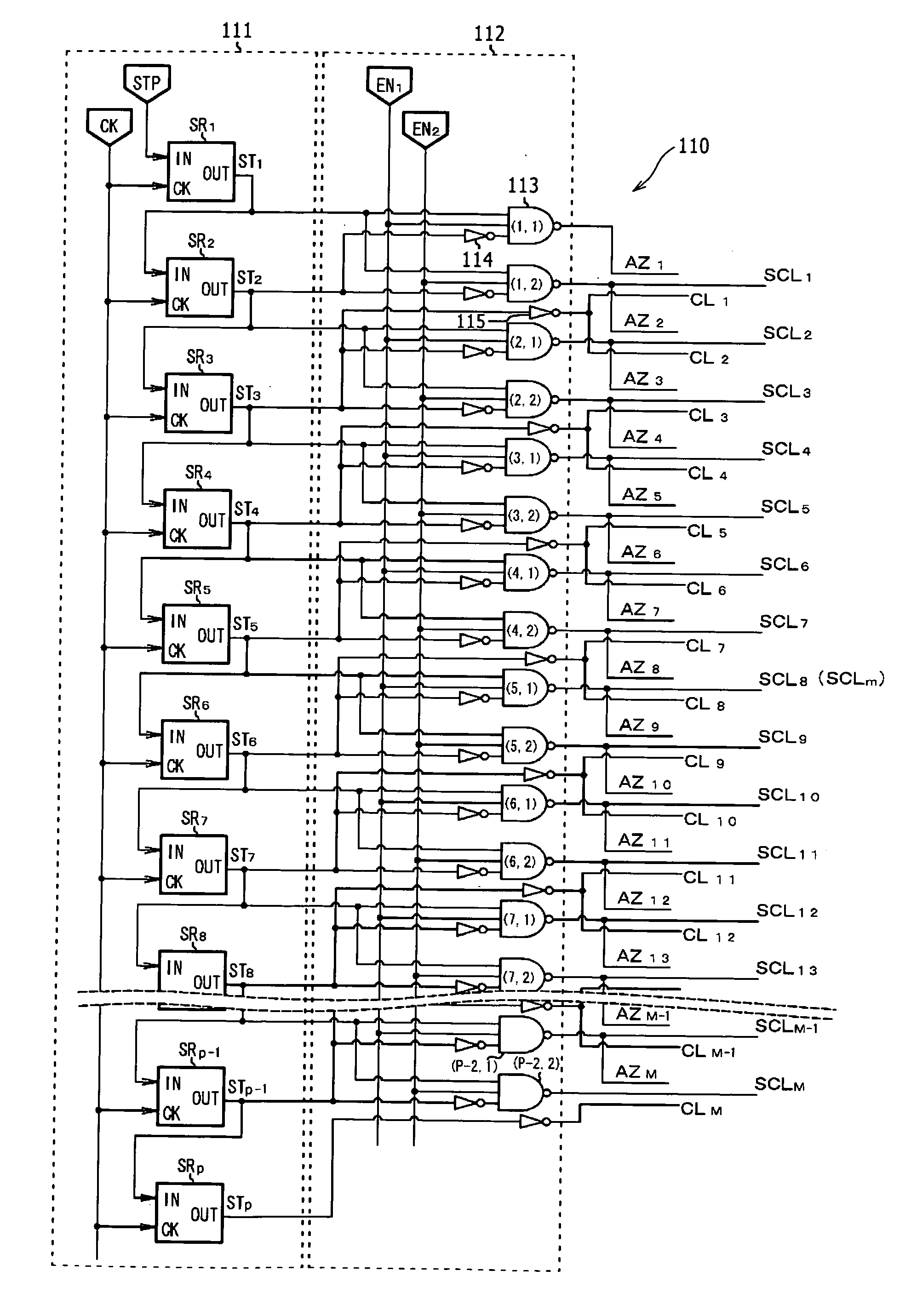
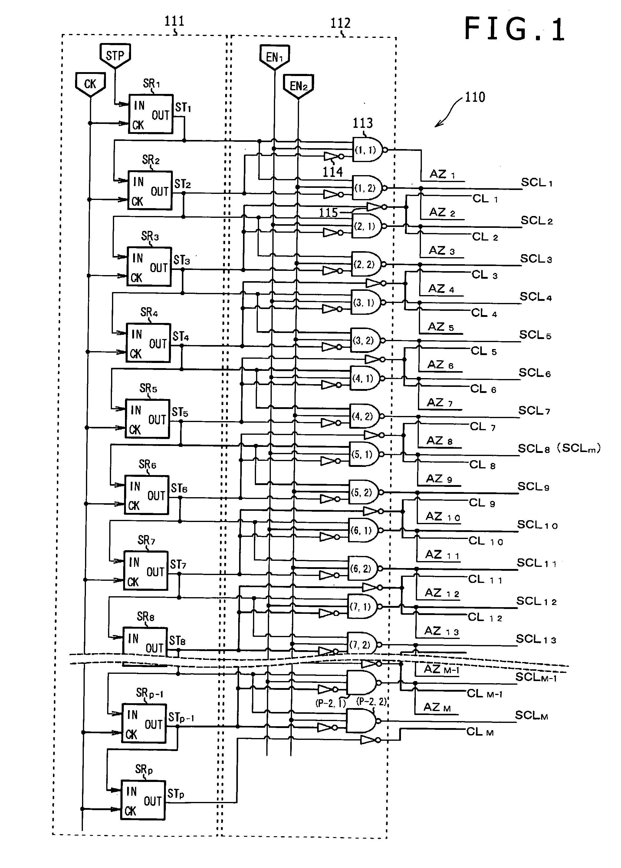
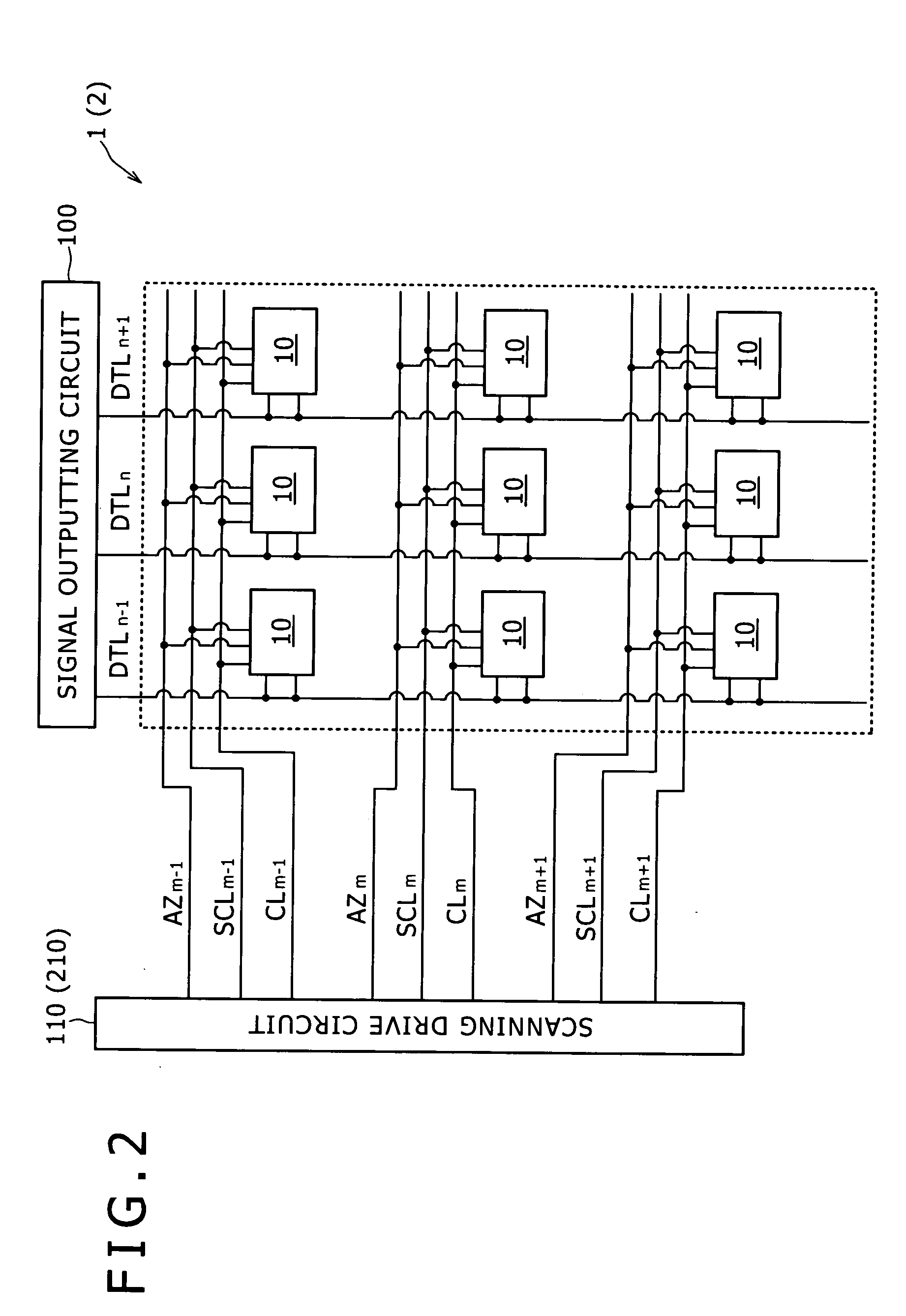
[0127]FIG. 1 is a circuit diagram showing a configuration of the scanning drive circuit 110 of Embodiment 1. FIG. 2 is a conceptual block diagram showing a configuration of the display device 1 of Embodiment 1 including the scanning drive circuit 110 shown in FIG. 1. FIG. 3 is a schematic timing chart explaining an operation of the scanning drive circuit 110 shown in FIG. 1. Also, FIG. 4 is an equivalent circuit diagram of a drive circuit 11 composing a display element 10 belonging to an m-th row (m=1, 2, 3, . . . , M) and an n-th column (n=1, 2, 3, . . . , N) in the display device 1 shown in FIG. 2. Firstly, an outline of the display device 1 will be described.
[0128]As s...
embodiment 2
[0220]A scanning drive circuit and a display device including the same according to the present invention will be described in detail hereinafter based on Embodiment 2. As shown in FIG. 2, the display device 2 of Embodiment 2 has the same configuration as that of the display device 1 of Embodiment 1 except that a scanning drive circuit 210 of the display device 2 of Embodiment 2 is different in configuration from the scanning drive circuit 110 of the display device 1 of Embodiment 1. Therefore, a description of the display device 2 is omitted in Embodiment 2 for the sake of simplicity.
[0221]FIG. 13 is a circuit diagram showing a configuration of the scanning drive circuit 210 of Embodiment 2. Also, FIG. 14 is a schematic timing chart explaining an operation of the scanning drive circuit 210 of Embodiment 2 shown in FIG. 13.
[0222]The scanning drive circuit 110 of Embodiment 1 uses the first enable signal EN1, and the second enable signal EN2. On the other hand, the scanning drive cir...
PUM
 Abstract
Description
Claims
Application Information
 - R&D
- Intellectual Property
- Life Sciences
- Materials
- Tech Scout
- Unparalleled Data Quality
- Higher Quality Content
- 60% Fewer Hallucinations
Browse by: Latest US Patents, China's latest patents, Technical Efficacy Thesaurus, Application Domain, Technology Topic, Popular Technical Reports.
© 2025 PatSnap. All rights reserved.Legal|Privacy policy|Modern Slavery Act Transparency Statement|Sitemap|About US| Contact US: help@patsnap.com


