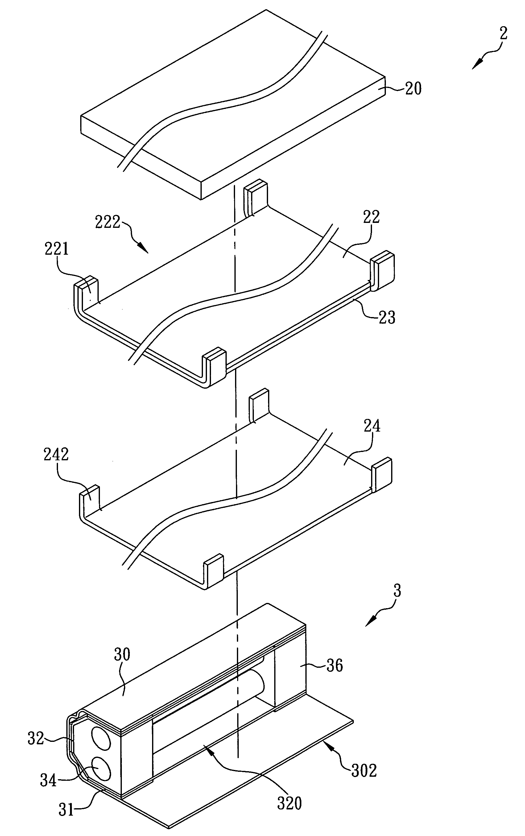
[0006]Therefore, it is a primary objective of the present invention to provide a heat dissipating structure of a backlight module, and the structure comprises two light emitting portions and a backlight portion, wherein the backlight portion includes a light guide plate, a back reflector and a metal clad, and the back side of the light guide plate is coupled to the front side of the back reflector, and two first protruding portions are extended from both sides of the back reflector respectively, and a dent is formed between two first protruding portions on either side, and the first protruding portions are bent upward and attached onto two corresponding sides of the light guide plate, and the back side of the back reflector is coupled to the front side of the metal clad by a first
adhesive layer, and two second protruding portions corresponding to the positions of the first protruding portions are protruded from both corresponding sides of the metal clad respectively, and the second protruding portions are bent upward and attached onto the first protruding portions. Further, the two light emitting portions individually comprise a metal cover, a lamp cup reflector, at least one lamp tube and a plurality of lamp holders, wherein a side of the lamp cup reflector is attached onto an internal side of the metal cover by a glue, and a containing groove is concavely disposed on another side of the lamp cup reflector. The containing groove contains at least one lamp tube and a plurality of lamp holders, and the lamp holders are coupled to both ends of the lamp tube, such that the lamp tube is not in contact with the lamp cup reflector. In addition, the two light emitting portions are installed on both corresponding sides of the backlight portion, and openings of the containing grooves face two corresponding sides of the backlight portion, such that the second protruding portions can be in contact with the lamp holders, and the lamp tube is aligned with the dent, and a thermal conducting plate is extended from a side of the metal cover and
proximate to the back reflector, and the thermal conducting plate is in contact with the back side of the metal clad. As a result, the heat produced by the lamp tube can be conducted to the metal clad through the lamp holder and the metal cover for dissipating the heat quickly and extending the life of the backlight module.
[0007]Another objective of the present invention is to provide a heat dissipating structure of a backlight module, and the heat dissipating structure comprises two light emitting portions and a backlight portion, and the two light emitting portions are installed onto both corresponding sides of the backlight portion respectively, wherein the two light emitting portions individually comprise a metal cover, a lamp cup reflector, at least one lamp tube and a plurality of lamp holders, and a side of the lamp cup reflector is attached onto an internal side of the metal cover, and a containing groove is concavely disposed on another side of the lamp cup reflector, and the containing groove contains at least one lamp tube and a plurality of lamp holders. The lamp holders are coupled to both ends of the lamp tube, such that the lamp cup reflector can completely reflect the
light source emitted from the lamp tube. Further, the backlight portion comprises a light guide plate, a back reflector and a metal clad, and the back side of the light guide plate is attached to the front side of the back reflector. The back side of the back reflector includes a first
adhesive layer for attaching the front side of the metal clad, and two protruding portions are extended from both sides of the metal clad respectively. The protruding portions are bent upward and attached onto both corresponding sides of the light guide plate, and a dent is formed between two protruding portions on either side. Further, the openings of the containing grooves of the two light emitting portions face the backlight portion, such that the protruding portions can be in contact with the lamp holders, and the lamp tube is aligned with the dent, and a thermal conducting plate is extended from a side of the metal cover
proximate to the back reflector, and the thermal conducting plate is in contact with the back side of the metal clad. Therefore, the heat at the lamp holders can be conducted directly to the metal clad or conducted to the metal clad through the metal cover to achieve a quick heat dissipating effect to prevent overheat of the light emitting portion and deterioration of the components of the backlight module.
[0008]A further objective of the present invention is to provide a metal clad with a larger area and design a protruding portion disposed on the metal clad for attaching the lamp holder directly, so that the heat at the lamp holders can be conducted quickly to the back side of the metal clad for heat dissipation, so as to reduce the total heat quantity of the lamp holders effectively. Further, the heat at a side of the lamp holder away from the protruding portion is conducted to the metal cover. Since the
thermal conductivity effect of the metal clad is superior to the
thermal conductivity effect of the metal cover, therefore the heat at the metal cover can be conducted to the back side of the metal clad through the thermal conducting plate and dispersed into the air to achieve the effect of dissipating a large quantity of heat quickly. The backlight module of the invention can maintain a
high heat dissipating performance without a back panel. In addition, the thickness of the metal clad is smaller than the thickness of the back panel, and thus the
material consumption of the metal clad is less than that of the back panel, and manufacturers can lower the production cost.
