
Catalysts compositions for use in fuel cells

a catalyst composition and fuel cell technology, applied in the manufacture of cell components, electrochemical generators, final product manufacturing, etc., can solve the problems of long time-consuming and labor-intensive, and the approach is faced with the challenge of rapid deactivation, so as to promote the formation of oxygen ions

Inactive Publication Date: 2009-12-10
THE UNIVERSITY OF AKRON
View PDF8 Cites 29 Cited by
  • Summary
  • Abstract
  • Description
  • Claims
  • Application Information

AI Technical Summary

Benefits of technology

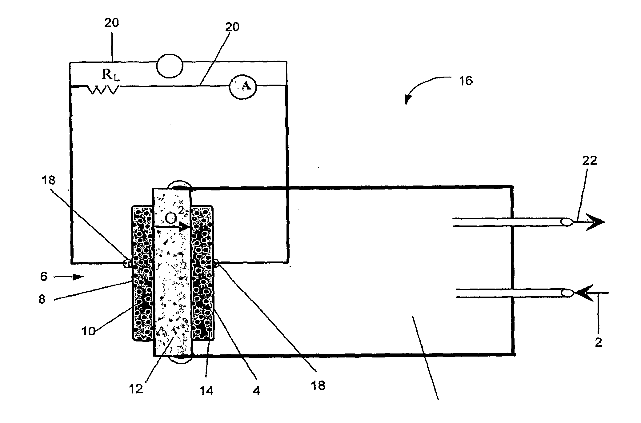
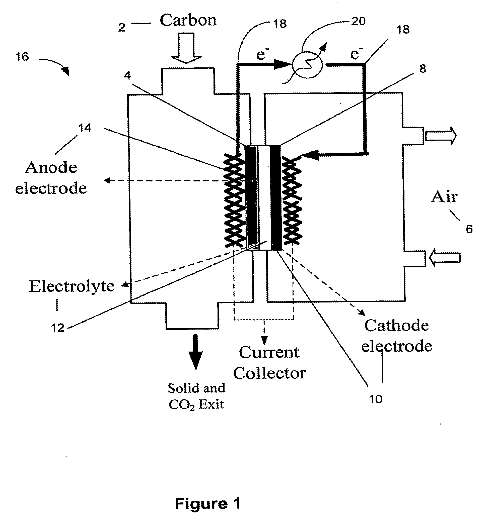
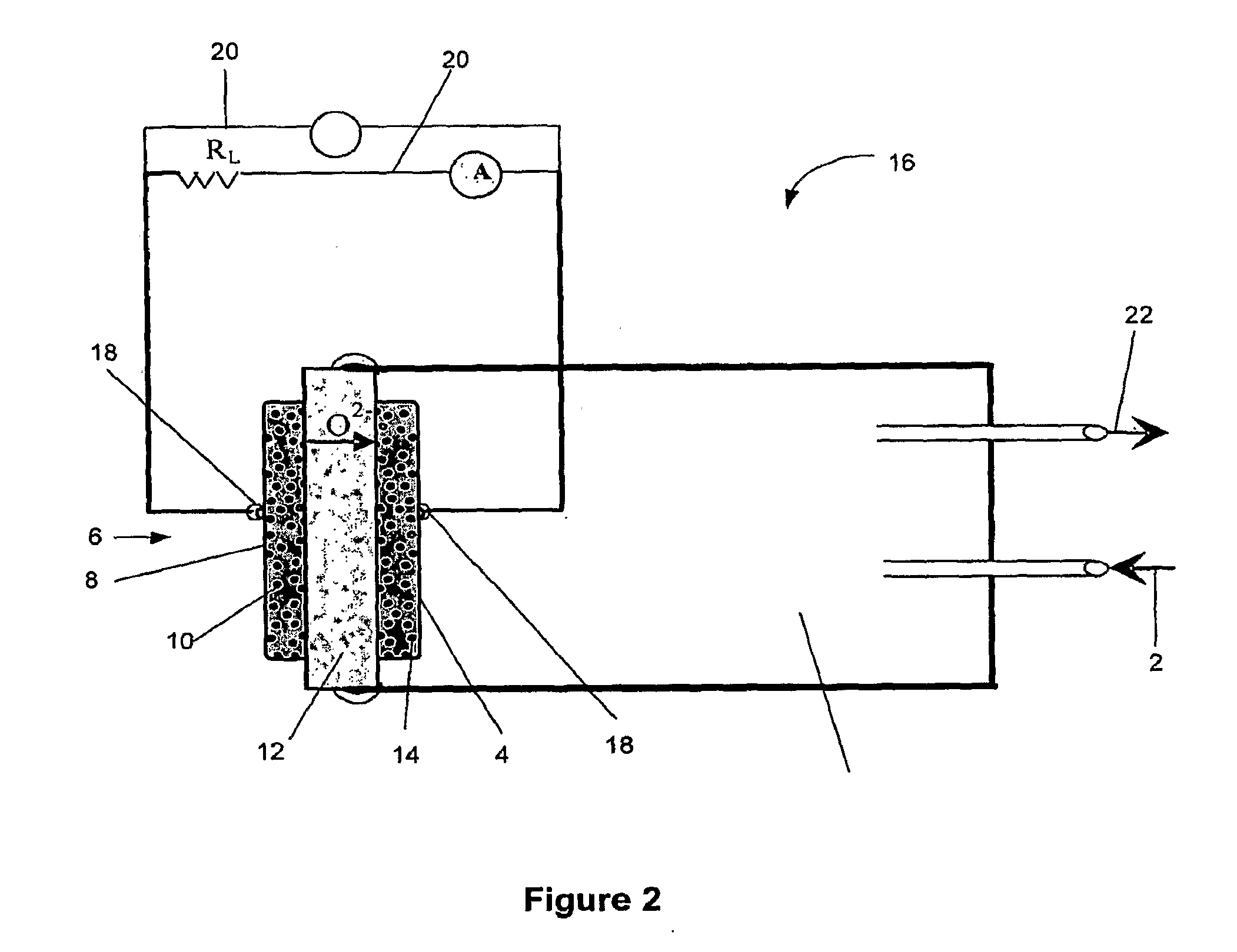
The present invention is about generating electrical energy from organic fuels using a solid-oxide fuel cell. The invention includes a cathode with a catalyst that promotes the formation of oxygen ions from an oxygen-containing source, an anode with a catalyst that promotes the direct oxidation of the organic fuel in the presence of the oxygen ions to produce electrical energy, a solid-oxide electrolyte in continuous contact with the anode and cathode, a means of feeding the organic fuel, a means for removing waste, a means for securing the anode, electrolyte, and cathode, and a means for drawing off electricity. The invention also includes a method of generating electrical power from an organic fuel by providing a fuel cell system, feeding the organic fuel to the system, removing waste from the system, forming oxygen ions from an oxygen-containing source at the cathode, transmitting the oxygen ions to the anode with anode catalysts, and catalyzing a reaction of the oxygen ions with the organic fuel to directly oxidize the fuel to produce a product and electrical energy.

Problems solved by technology

The separate gasification and reforming steps requiring a substantial influx of thermal energy, and with heat recovery being low, an inefficient process results.
This is resulted from the build up of flyash and a poisoning of electrodes by sulfur compounds in coals.
The long period of operation for these fuel cells can only be achieved by using high purity carbon as the fuel.
One issue with the liquid anode approach is that such an approach faces the challenge of rapid deactivation.

Method used


Image

  • Catalysts compositions for use in fuel cells
  • Catalysts compositions for use in fuel cells
  • Catalysts compositions for use in fuel cells

Examples


second embodiment

[0090]A second embodiment involves loading 1.0 g of devolatilized Ohio # 5 coal (i.e., coke), and re-heating back to 800° C. under flowing 120 cc / min N2 and 25 cc / min H2. Coke is used for avoiding the formation of coal tar which could smear the quartz, affecting direct observation of flyash and coke particle distribution. This is to insure that Ni is in the reduced state prior to determining the performance of fuel cell with coke as a fuel.

third embodiment

[0091]The third embodiment determines the fuel cell performance with coke as fuel in the presence of inert gas, N2. During these three experimental embodiments, fuel cell performances and effluent gas composition are constantly monitored during the reduction of the anode catalyst as well as during the oxidation of coke and coke / H2 using a Solarton 1400 CellTest system, GC, and MS spectrometer.

[0092]FIG. 18 shows the characteristic V-I curve obtained when operating the fuel cell on H2, devolatilized coal (i.e. coke), and coke+H2 at 800° C. In embodiment #1, the fuel cell was exposed to H2 / N2. During this initial reduction of anode catalyst, OCV developed relatively slowly, reaching a maximum of 0.9 Volts after 1 hour of operation. A stable maximum current density of 500 mA / cm2 was achieved after 5 hours of operation. The VI curve measured at t−5 hours is shown in FIG. 18. Previous attempts to conduct this part of the experiment resulted in short circuiting of the fuel cells, possibly...


PUM

PropertyMeasurementUnit
temperatureaaaaaaaaaa

Abstract

The present invention generally relates to the generation of electrical energy from a solid-state fuel. In one embodiment, the present invention relates to a solid-oxide fuel cell for generating electrical energy from a carbon-based fuel, and to catalysts for use in a solid-oxide fuel cell.

Description

RELATED APPLICATION DATA[0001]This application claims priority to previously filed U.S. Provisional Patent Application No. 60 / 844,228, filed on Sep. 13, 2006, and PCT / US2007 / 019853, filed Sep. 13, 2007, entitled “Catalysts Compositions for Use in Fuel Cells”, which is incorporated by reference herein in its entirety.FIELD OF THE INVENTION[0002]The present invention generally relates to the generation of electrical energy from a solid-state fuel. In one embodiment, the present invention relates to a solid-oxide fuel cell for generating electrical energy from a carbon-based fuel, and to catalysts for use in a solid-oxide fuel cell.BACKGROUND OF THE INVENTION[0003]The direct use of carbon in a fuel cell to generate electricity is an attractive approach for power generation. A number of carbonate and alkali fuel cells have been used for the direct generation of electricity from treated coal (i.e., ultra low sulfur / ash coal).[0004]Conventional solid-oxide fuel cells utilize an electrolyt...

Claims


Application Information

Patent Timeline
Patent Type & Authority Applications(United States)
IPC IPC(8): H01M8/10H01M8/04
CPCH01M4/90H01M4/9025H01M4/9033H01M4/905H01M4/9058H01M4/92Y02E60/526H01M8/1253H01M8/143H01M8/22H01M2008/147Y02E60/521Y02E60/525H01M8/1233Y02E60/50Y02P70/50
Inventor CHUANG, STEVEN S.C.
Owner THE UNIVERSITY OF AKRON
Learn More