Fast p-i-n photodetector with high responsitivity

a photodetector and fast pin technology, applied in the field of high responsivity fast pin photodetectors, can solve the problems of loss of detector responsivity, shallow trenches, and more difficult integration of trenches with semiconductor-on-insulator technology

Active Publication Date: 2009-12-10
IBM CORP
View PDF14 Cites 51 Cited by
  • Summary
  • Abstract
  • Description
  • Claims
  • Application Information

AI Technical Summary

Benefits of technology

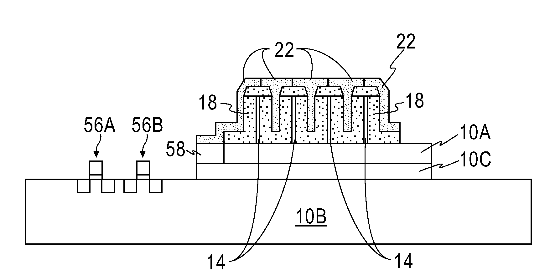
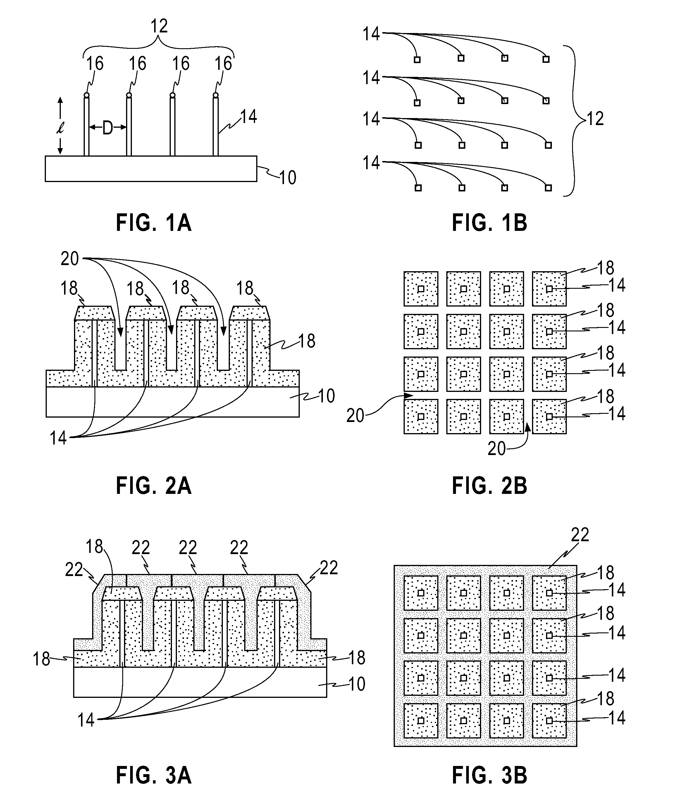
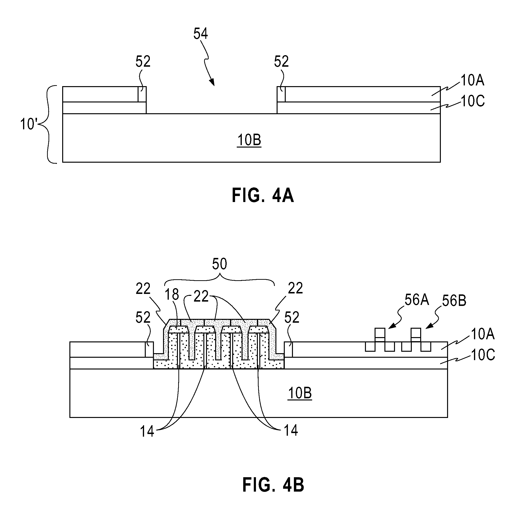
[0011]The inventive lateral p-i-n photodetector electrodes are comprised of the “core” semiconductor nanowires of the first conductivity type and a “shell” of the epitaxial semiconductor material of the second conductivity type. In between the core and the shell is a thick intrinsic semiconductor film which forms the intrinsic (i.e., “i”) region of the lateral p-i-n photodetector. The lateral p-i-n photodetector of the present invention is not formed within DRAM trenches, does not require high aspect ratio RIE and can be integrated easily with bulk or SOI CMOS technology.
[0013]In the inventive structure, the bulk of the absorption of photons occurs in the intrinsic semiconductor regions between nanowires. The issue of a large surface area to volume ratio presented by nanowires (which leads to high recombination rate due to the surface recombination) is eliminated in the inventive p-i-n photodetector by passivating the semiconductor nanowires with an epitaxially grown intrinsic semiconductor material and a second conductivity type semiconductor material, which effectively fills the gaps between nanowires and eliminates the nanowires' sidewall surfaces.

Problems solved by technology

Also, it is more difficult to integrate trenches with semiconductor-on-insulator (SOI) technology due to the presence of the buried insulating layer.
Additionally, and on one hand, since the RIE process can produce trenches with finite aspect ratio of depth over width, reducing the trench width will result in shallower trenches and therefore loss of detector responsivity.
On another hand, wide trenches reduce the intrinsic silicon available for carrier absorption.

Method used


Image

  • Fast p-i-n photodetector with high responsitivity
  • Fast p-i-n photodetector with high responsitivity
  • Fast p-i-n photodetector with high responsitivity

Examples


Embodiment Construction

[0039]The present invention, which provides a fast p-i-n photodetector with high responsivity and a method of fabricating the same, will now be described in greater detail by referring to the following discussion and drawings that accompany the present application. It is noted that the drawings of the present application are provided for illustrative purposes only and, as such, the drawings are not drawn to scale.

[0040]In the following description, numerous specific details are set forth, such as particular structures, components, materials, dimensions, processing steps and techniques, in order to provide a thorough understanding of the present invention. However, it will be appreciated by one of ordinary skill in the art that the invention may be practiced without these specific details. In other instances, well-known structures or processing steps have not been described in detail in order to avoid obscuring the invention.

[0041]It will be understood that when an element as a layer...


PUM


Abstract

A lateral p-i-n photodetector is provided that includes an array of vertical semiconductor nanowires of a first conductivity type that are grown over a semiconductor substrate also of the first conductivity type. Each vertically grown semiconductor nanowires of the first conductivity type is surrounded by a thick epitaxial intrinsic semiconductor film. The gap between the now formed vertically grown semiconductor nanowires-intrinsic semiconductor film columns (comprised of the semiconductor nanowire core surrounded by intrinsic semiconductor film) is then filled by forming an epitaxial semiconductor material of a second conductivity type which is different from the first conductivity type. In a preferred embodiment, the vertically grown semiconductor nanowires of the first conductivity type are n+ silicon nanowires, the intrinsic epitaxial semiconductor layer is comprised of intrinsic epitaxial silicon, and the epitaxial semiconductor material of the second conductivity type is comprised of p+ silicon.

Description

CROSS-REFERENCE TO RELATED APPLICATIONS[0001]This application is a divisional of U.S. patent application Ser. No. 12 / 124,617, filed May 21, 2008.[0002]The present invention relates to a semiconductor structure and a method of fabricating the same. More particularly, the present invention relates to a fast photodetector having high responsitivity and a method of fabricating such a photodetector. Even more particularly, the present invention relates to a fast p-i-n photodetector having high responsivity using nanowire electrodes that are vertically oriented relative to a surface of an underlying semiconductor substrate.BACKGROUND[0003]The absorption length of 850 nm light in silicon is 15-20 microns, which is much longer than the 1-2 microns absorption length of typical III-V compound semiconductors such as GaAs at this wavelength. As a result, high speed silicon photodetectors are often designed with a lateral structure, rather than a vertical structure, in an attempt to decouple the...

Claims


Application Information

Patent Timeline
Patent Type & Authority Applications(United States)
IPC IPC(8): H01L31/18
CPCB82Y10/00Y02E10/547H01L29/0673H01L29/0676H01L31/03529H01L31/105H01L31/1804Y10S977/762Y10S977/932Y10S977/954Y10S977/712Y10S977/721Y10S977/763Y10S977/749H01L29/0665Y02P70/50
Inventor COHEN, GUY M.
Owner IBM CORP
Why Eureka
Try Eureka