Misfire determination device and misfire determination method for internal combustion engine and vehicle

a technology of misfire determination and internal combustion engine, which is applied in the direction of electric devices, machines/engines, motors/generators/converter stoppers, etc., can solve the problems of interference with accurate detection of misfire, and achieve the effects of increasing influence, high accuracy, and high accuracy

Active Publication Date: 2009-12-17
TOYOTA JIDOSHA KK
View PDF3 Cites 34 Cited by
  • Summary
  • Abstract
  • Description
  • Claims
  • Application Information

AI Technical Summary

Benefits of technology

[0025]In the misfire determination method of the invention that uses the constant relation value to calculate the resonance influence component, the method may include learning a constant relation value in a one-cylinder lean operation state that is an operation state of the internal combustion engine in which a fuel injection amount of any one of cylinders of the internal combustion engine is reduced to increase an air / fuel ratio of the cylinder higher than an air / fuel ratio of other cylinders, the constant relation value being obtained by dividing the rotation angle acceleration of the output shaft calculated on the basis of the output shaft rotation speed by the helix angle calculated from the output shaft rotation speed and the post-stage shaft rotation speed, and calculating the resonance influence component using the learned constant relation value. Thus, the misfire of the internal combustion engine can be determined with high accuracy by calculation of the resonance influence component using a more adequate constant relation value, even when the constant relation value changes with time. Further, a more adequate constant relation value can be learned in the one-cylinder lean operation with the increased influence component of resonance.
[0026]In the misfire determination method of the invention that uses the constant relation value to calculate the resonance influence component, the method may reflect a gain and a phase corresponding to the output shaft rotation speed on a spring force component obtained by integral calculation of the constant relation value multiplied by the helix angle, to calculate the resonance influence component. The resonance influence component by the torsion element may be assumed as the sum of a component based on a spring force of the torsion element and a component based on a damping force, and the component based on the damping force may be calculated as a gain and a phase relative to the component based on the spring force. The gain and the phase change depending on a frequency of a misfire (corresponding to the rotation speed of the output shaft), and thus the gain and the phase depending on the rotation speed of the output shaft are reflected on the component based on the spring force, thereby allowing more proper calculation of the resonance influence component. This allows more proper determination of the misfire of the internal combustion engine.
[0027]In the misfire determination method of the invention, the method may calculate the resonance influence component by performing a filtering processing of a component calculated on the basis of the output shaft rotation speed and the post-stage shaft rotation speed, using a high-pass filter without damping of the frequency of resonance. The filtering processing may be a processing of a component calculated on the basis of the output shaft rotation speed and the post-stage shaft rotation speed, using a comb-like filter leaving multiple order frequency components of the frequency of resonance with a gain=1 and a phase=0. Thus, components of the band of frequencies other than the frequency of resonance can be removed from the resonance influence component. Particularly, when components before the filtering processing are calculated using integral calculation, the filtering processing can also remove components accumulated by the integral calculation. This allows determination of the misfire of the internal combustion engine with higher accuracy.

Problems solved by technology

This interferes with accurate detection of a misfire of any cylinder of the engine on the basis of the rotational variation of the crank angle.

Method used


Image

  • Misfire determination device and misfire determination method for internal combustion engine and vehicle
  • Misfire determination device and misfire determination method for internal combustion engine and vehicle
  • Misfire determination device and misfire determination method for internal combustion engine and vehicle

Examples


Embodiment Construction

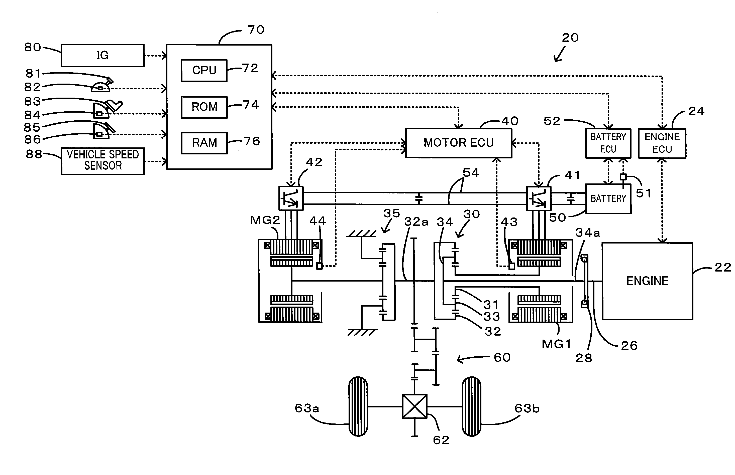
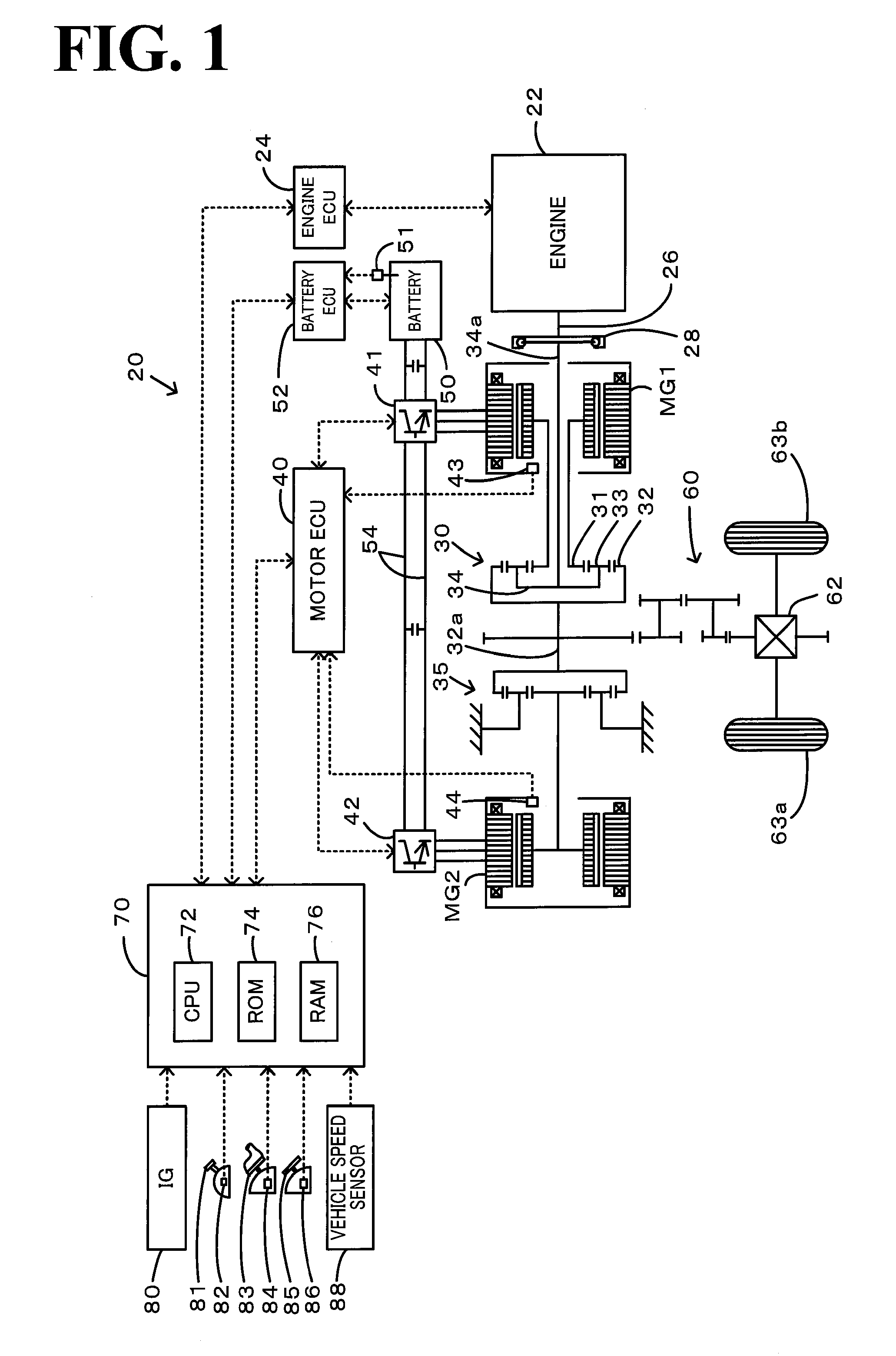
[0037]Now, the best mode for carrying out the present invention will be described with reference to an embodiment. FIG. 1 is a schematic block diagram of a configuration of a hybrid vehicle 20 including a misfire determination device for an internal combustion engine according to an embodiment of the present invention. The hybrid vehicle 20 in the embodiment includes, as shown, an engine 22, a three shaft-type power distribution and integration mechanism 30 connected to a crankshaft 26 as an output shaft of the engine 22 via a damper 28 as a torsion element, a motor MG1 that is connected to the power distribution and integration mechanism 30 and can generate electric power, a reduction gear 35 mounted to a ring gear shaft 32a connected to the power distribution and integration mechanism 30, a motor MG2 connected to the reduction gear 35, and a hybrid electronic control unit 70 that controls the entire vehicle. An engine electronic control unit 24 that mainly controls the engine 22, ...


PUM


Abstract

A damper post-stage rotation speed in a post-stage of a damper calculated from motor rotation speeds and an engine rotation speed are used to calculate a resonance influence component, and the resonance influence component is subtracted from the engine rotation speed to calculate a determination rotation speed. Then, the determination rotation speed is used to determine a misfire of an engine. This allows determination of the misfire of the engine with higher accuracy even if resonance caused by torsion of the damper occurs.

Description

TECHNICAL FIELD [0001]The present invention relates to a misfire determination device and a misfire determination method for an internal combustion engine and a vehicle, and more particularly to a misfire determination device for an internal combustion engine that determines a misfire of a multicylinder internal combustion engine in which an output shaft is connected to a post-stage shaft in a post-stage via a torsion element, a misfire determination method for determining the misfire of the internal combustion engine, and a vehicle including the misfire determination device.BACKGROUND ART [0002]In a vehicle in which a motor is used to perform the damping control to cancel a torque change of a crankshaft of the engine, a conventionally proposed misfire determination device for an internal combustion engine of this type calculates a torque correction amount to correct torque outputted from the motor for damping control by the motor, and detects a misfire state of the engine on the ba...

Claims


Application Information

Patent Timeline
Patent Type & Authority Applications(United States)
IPC IPC(8): G01M15/04H02P6/08B60L50/15B60L50/16F02D29/02F02D45/00
CPCB60K6/445B60W10/06B60W10/08B60W30/20F02D41/008F02D41/1498F02D2200/1015F02D2041/1432Y02T10/6286Y02T10/6239F02D2041/1433G01M15/11F02D41/2451F02D41/22B60K1/02B60K6/365B60K6/40B60L2220/14B60L2240/441B60L2270/145B60W20/00B60W2510/0638B60L50/61B60L50/16Y02T10/62Y02T10/7072Y02T10/70
Inventor SUZUKI, TAKASHI
Owner TOYOTA JIDOSHA KK
Why Eureka
Try Eureka