Pre-Chamber Spark Plug

a spark plug and chamber technology, applied in the field of prechamber spark plugs, can solve the problems of poor fuel economy, inability of conventional spark plugs to effectively ignite a lean fuel mixture in the cylinder of the operating engine, and inability to complete combustion, so as to reduce electrode erosion and maximize the life of the spark plug

Active Publication Date: 2009-12-17
WOODWARD GOVERNOR CO
View PDF21 Cites 69 Cited by
  • Summary
  • Abstract
  • Description
  • Claims
  • Application Information

AI Technical Summary

Benefits of technology

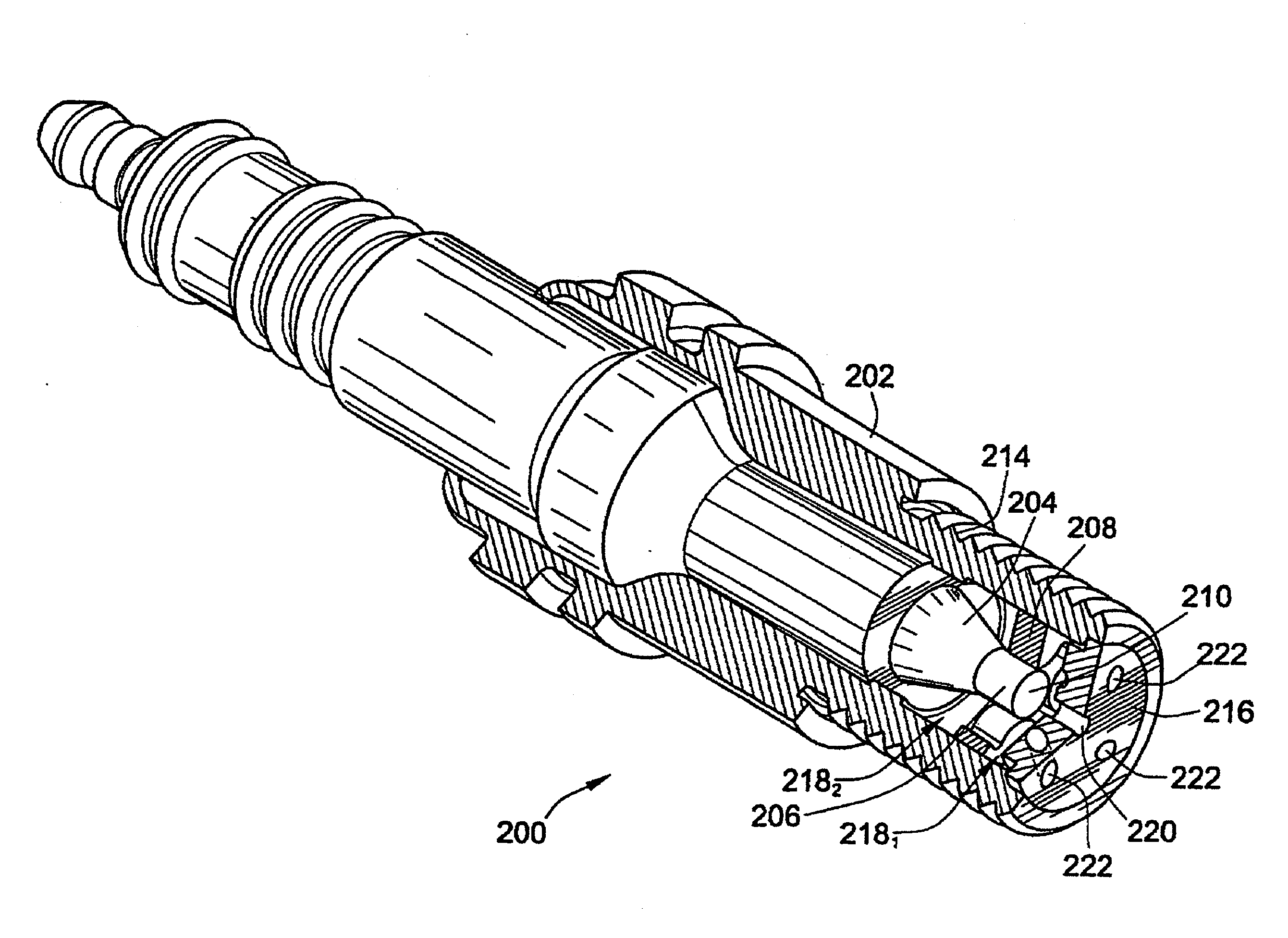
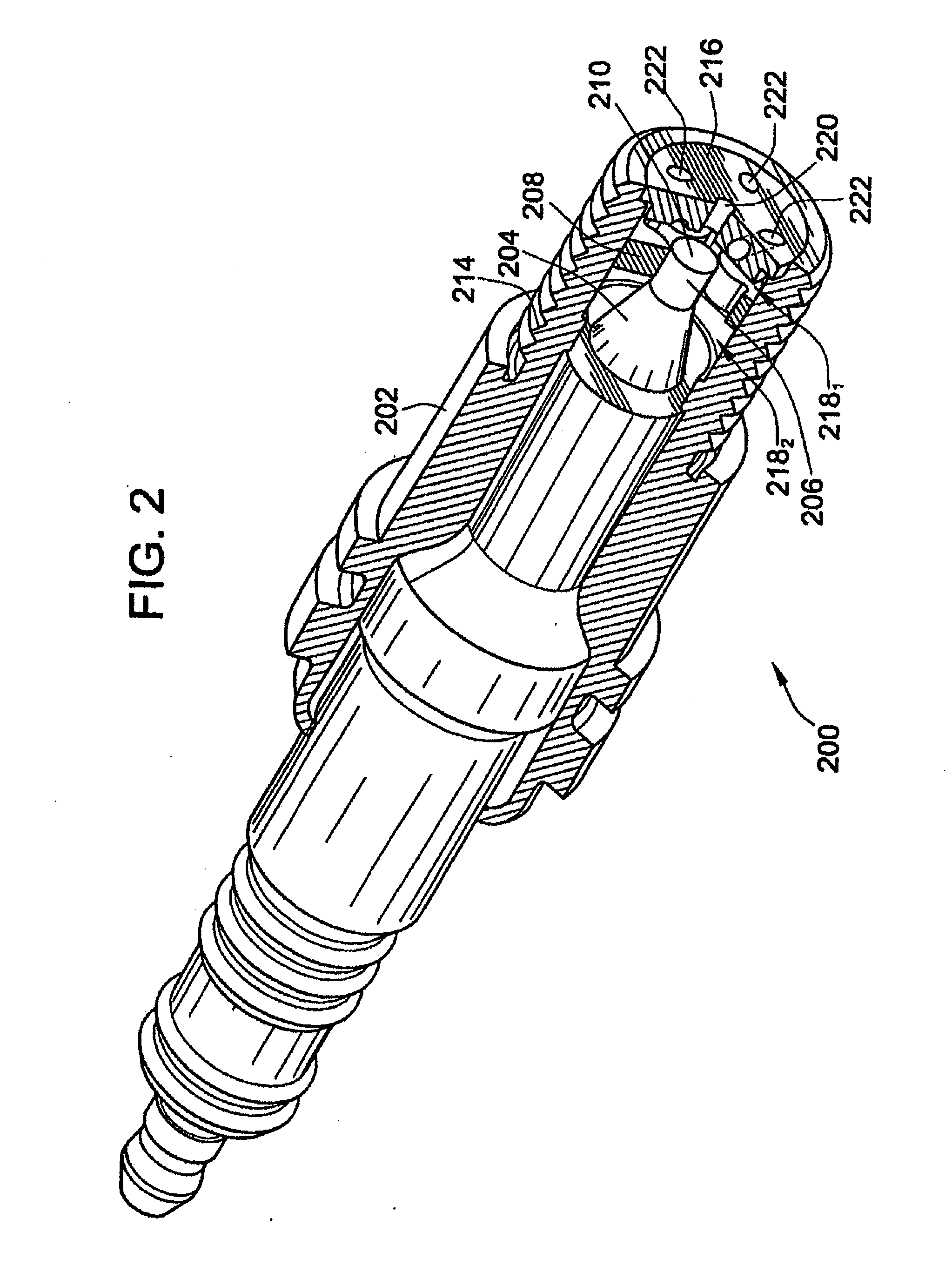
[0009]The invention provides a method and apparatus to maximize spark plug life in pre-chamber spark plugs operating with ultra-lean mixtures and / or at elevated engine BMEP. Electrode erosion is reduced by spreading the discharge energy per electrode unit surface area over a wider area, maintaining fuel concentration in the spark gap, controlling gas static pressure at the time of electrical discharge, and maintaining electrode temperature within its safe operating range.

Problems solved by technology

The lean fuel mixture often results in misfires, detonation, incomplete combustion and poor fuel economy.
One factor that can lead to such events is the poor ability of conventional spark plugs to effectively ignite a lean fuel mixture in the cylinder of the operating engine.
The fast burning of fuel in the pre-chamber cavity can result in highly penetrating jets of flames into the engine combustion chamber.
One problem that the prior art does not address is spark plug operation with ultra-lean air / fuel mixtures (lambda>1.75) and high BMEP (Brake Mean Effective Pressure) (>18 bars).
At such operating conditions, the spark plug life tends to be very short.
As a result, commercialization of high efficiency and high power density gas engines is not practical.
The prior art also does not address the issue of water condensation inside the spark plug pre-chamber and in between the electrodes causing short circuit and plug misfire.
Additionally, the prior art does not address the issue of plug surfaces overheating and causing preignition.

Method used


Image

  • Pre-Chamber Spark Plug
  • Pre-Chamber Spark Plug
  • Pre-Chamber Spark Plug

Examples


Embodiment Construction

[0031]Embodiments of the invention provide a method and apparatus to maximize spark plug life in pre-chamber spark plugs operating with ultra-lean mixtures and at elevated engine BMEP.

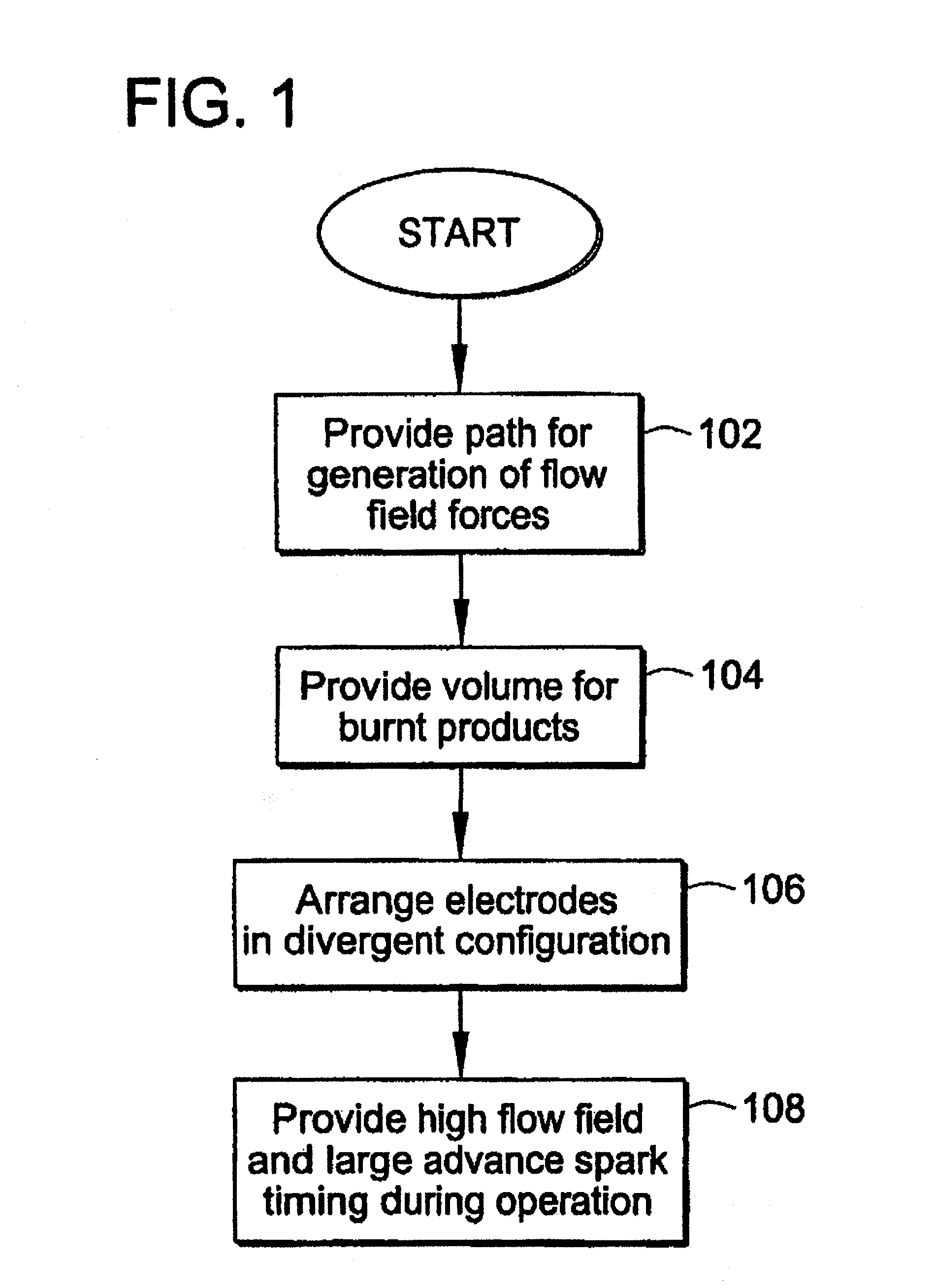
[0032]FIG. 1 is a flow chart illustrating the overall steps taken to maximize the operational life of a pre-chamber spark plug. Step 102 calls for providing a path for the generation of field flow forces. In one embodiment of the invention, a pre-combustion chamber of the pre-chamber spark plug is configured to receive an air-fuel mixture in a manner that generates field flow forces within the chamber. Step 104 calls for providing a volume for burnt products that result from the combustion process within the pre-combustion chamber. In an embodiment of the invention, a ground electrode is positioned to create a volume for burnt products within the pre-combustion chamber. Step 106 calls for the spark plug electrodes to be arranged in a divergent configuration. To maximize the life of the spark plug, step...


PUM


Abstract

A method and apparatus to maximize spark plug life in pre-chamber spark plugs operating with ultra-lean mixtures and/or elevated engine BMEP is presented. Electrode erosion is reduced by spreading discharge energy over a wider surface area, maintaining fuel concentration in the spark gap, controlling gas static pressure during discharge, and maintaining safe electrode temperature. Energy is spread via a swirling effect created by periphery holes in an end cap, resulting in a lower specific energy discharge at the electrodes. Divergently configured electrodes reduce the spark voltage at high operating pressures and the energy required for ignition. The flow field generated at the electrodes prevents electrical shorts due to water condensation and avoids misfire. The center electrode insulation provides an effective heat transfer path to prevent electrode overheating and pre-ignition. The volume behind the electrodes provides a volume for burnt products from previous combustion cycles and leads to more reliable ignition.

Description

CROSS-REFERENCE TO RELATED PATENT APPLICATIONS[0001]This patent application is a continuation-in-part of co-pending U.S. patent application Ser. No. 10 / 547,623, filed Aug. 30, 2005, which claims the benefit of PCT / US2005 / 020121 filed Jun. 7, 2005, the entire teachings and disclosure of which are incorporated herein by reference thereto.FIELD OF THE INVENTION[0002]This invention pertains to pre-chamber spark plugs, and more particularly to pre-chamber spark plugs for lean burn engines.BACKGROUND OF THE INVENTION[0003]Engines operating on gaseous fuels, such as natural gas, are commonly supplied with a lean fuel mixture, which is a mixture of air and fuel containing a relatively high ratio of air to fuel. The lean fuel mixture often results in misfires, detonation, incomplete combustion and poor fuel economy. One factor that can lead to such events is the poor ability of conventional spark plugs to effectively ignite a lean fuel mixture in the cylinder of the operating engine. More ef...

Claims


Application Information

Patent Timeline
Patent Type & Authority Applications(United States)
IPC IPC(8): H01T13/20
CPCF02B19/08F02B19/12Y02T10/125H01T13/54H01T13/467Y02T10/12H01T13/32H01T21/02
Inventor TOZZI, LUIGI P.
Owner WOODWARD GOVERNOR CO
Why Eureka
Try Eureka