Method and system for enhanced remote detection of low concentration vapors

Active Publication Date: 2009-12-17
THE BOEING CO
View PDF8 Cites 9 Cited by
  • Summary
  • Abstract
  • Description
  • Claims
  • Application Information

AI Technical Summary

Benefits of technology

[0008]This need for a method and system for enhanced remote detection of low concentration vapors, as well as a unique, nonobvious, and advantageous method and system, is satisfied. None of the known methods and systems provide all of the numerous advantages discussed herein. Unlike known methods and systems, embodiments of the method and system may provide one or more of the following advantages: provides a method and system for detecting target materials such as hazardous solid and liquid materials, including chemical agents, biological agents, explosive agents, or other hazardous substances, by changing the conditions of the target materials for the purpose of improving detectability of such materials; provides a method and system for enhanced remote detection of low concentration vapors that more readily achieves performance improvements and increases vapor concentration by an order of magnitude or greater; provides a method and system that increases the probability of remote detection of a material vapor by effectively increasing the interaction between the material vapor and the sensor radiation to render the target materials detectable at all ranges of interest using existing remote sensor technology, where such enhancement makes it particularly valuable for the remote detection of target materials having very low ambient vapor pressures which can make the difference between a target material being undetectable and detectable; provides a method and system for enhanced remote detection of low concentration vapors that uses a heating source to heat the solid and / or liquid target materials from a remote or standoff distance, which in turn, increases the vapor pressure of the solid and / or liquid target materials, thereby increasing the vapor concentration of the surrounding environment, and that uses a passive and / or active remote sensing system to exploit the increased vapor concentration to substantially improve the probability of detection of the solid and / or liquid target materials; and, provides a method and system that may be used in security screening measures, law enforcement applications, forensic analysis, environmental applications, homeland security, military applications, and commercial applications.
[0009]In an embodiment of the disclosure, there is provided a method for detecting a material comprising the steps of: targeting the material for analysis; heating the material with a heating source from a remote distance to effectively increase a temperature of the material and to effectively increase a vapor pressure of the material in an environment adjacent to the material; measuring with a sensor a material vapor in the adjacent environment from the remote distance; and, detecting the identity of the material using data generated during the measuring step.

Problems solved by technology

None of the known methods and systems provide all of the numerous advantages discussed herein.

Method used


Image

  • Method and system for enhanced remote detection of low concentration vapors
  • Method and system for enhanced remote detection of low concentration vapors
  • Method and system for enhanced remote detection of low concentration vapors

Examples


embodiment 10

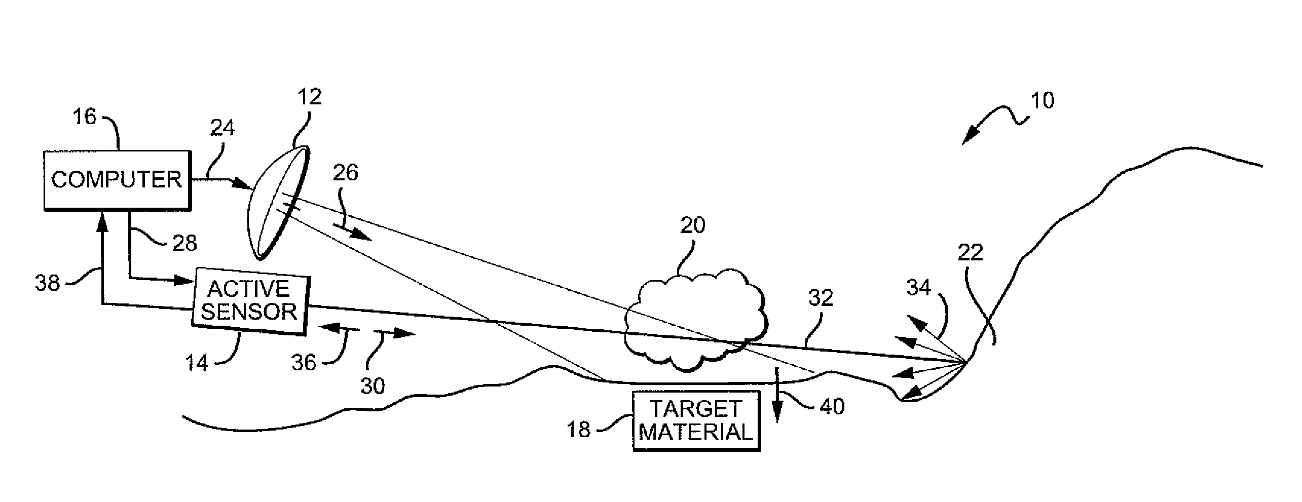
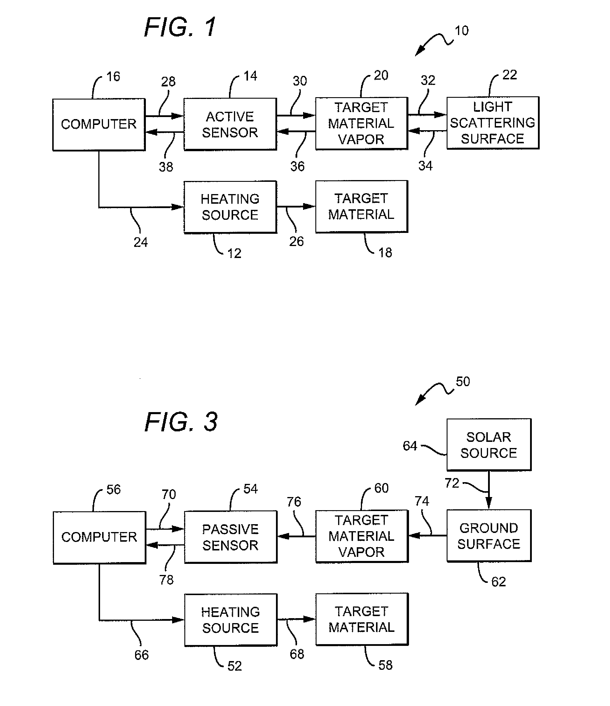
[0022]Referring now to the drawings, FIG. 1 is a block diagram of a first disclosed embodiment 10 of the method with a heating source and an active sensor. FIG. 1 shows a heating source 12, an active sensor 14, a computer 16, a target material 18, a target material vapor 20, and a light scattering surface 22. The computer 16 initiates a heating beam generator control signal 24, such as a microwave generator control signal, to the heating source 12. The heating source 12, such as a high power microwave beam generator, heats the target material 18 with a heating beam 26, such as a microwave beam. The heating source 12 heats the target material 18 for an effective period of time so that the temperature of the target material increases and the vapor pressure of the target material increases. The target material vapor 20 is emitted from the target material 18 upon heating. The computer 16 initiates a control and sensor signal 28, such as a laser control, to activate the active sensor 14....

embodiment 50

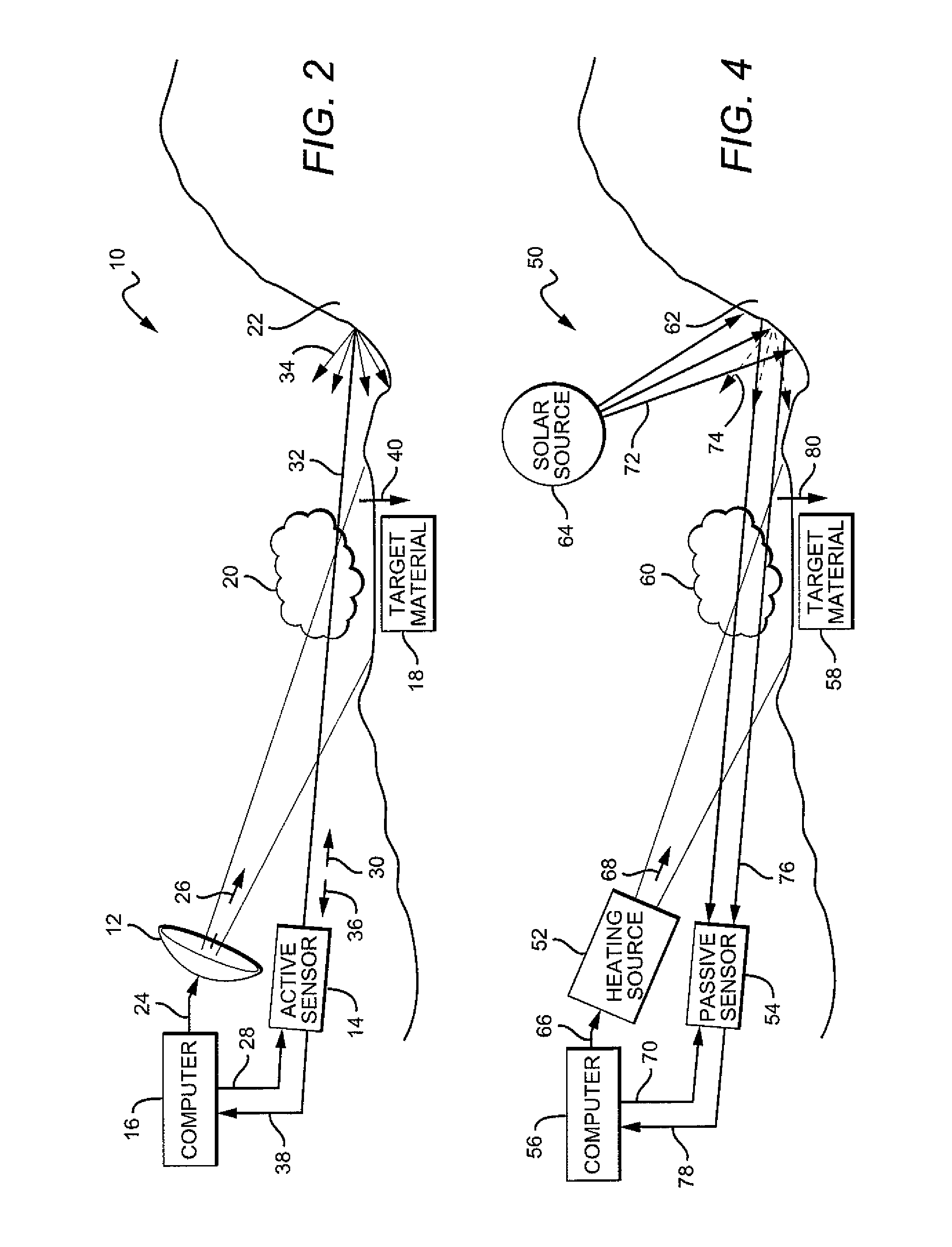
[0024]FIG. 3 is a block diagram of a second disclosed embodiment 50 of the method with a heating source and a passive sensor. FIG. 3 shows a heating source 52, a passive sensor 54, a computer 56, a target material 58, a target material vapor 60, a ground surface 62, and a solar source 64. The computer 56 initiates a heating beam generator control signal 66, such as a high power infrared laser signal, to the heating source 52. The heating source 52, such as a high power infrared laser, heats the target material 58 with a heating beam 68, such as an infrared laser beam. The heating source 52 heats the target material 58 for an effective period of time so that the temperature of the target material increases and the vapor pressure of the target material increases. The target material vapor 60 is emitted from the target material 58 upon heating. The computer 56 initiates a control and sensor signal 70 to activate the passive sensor 54. The solar source 64, such as the sun, emits solar r...


PUM


Abstract

There is provided a method for detecting a target material, preferably a solid or liquid target material. The method may comprise the steps of targeting a material for analysis, heating the material with a heating source from a remote distance to effectively increase a temperature of the material and to effectively increase a vapor pressure of the material in an environment adjacent to the material, measuring with a sensor the material vapor in the adjacent environment from the remote distance, and detecting the identity of the material using data generated during the measuring step. There is also provided a system for detecting a target material having a low vapor pressure comprising a first energy generating source, a sensor for measuring properties of gaseous materials from a standoff distance, the sensor producing data, and a computer for determining the target material based on the data produced by the sensor.

Description

BACKGROUND OF THE DISCLOSURE[0001]1) Field of the Disclosure[0002]The disclosure relates to a method and system for enhanced remote detection of low concentration vapors, and more particularly to a method and system for enhanced remote detection of low concentration vapors using a heating source and a sensor.[0003]2) Description of Related Art[0004]There is an ongoing need for methods and systems capable of early remote detection of hazardous and controlled solid and liquid materials, such as chemical agents, biological agents, explosive agents, narcotics and other hazardous and controlled substances, and in particular, solid and liquid materials having very low vapor pressures. Every solid and liquid material has some vapor pressure, with solid materials typically having very low vapor pressures at ambient or room temperature, and liquid materials having higher vapor pressures at ambient or room temperature. In particular, explosive solid materials such as TNT (trinitrotoluene), ha...

Claims


Application Information

Patent Timeline
IPC IPC(8): G01J3/44G01N7/00G06F19/00
CPCG01N1/4022G01N21/3518G01N2021/653G01N21/718G01N2021/1793G01N21/3563
Inventor NORMAN, JEFFREY B.
Owner THE BOEING CO
Why Eureka
Try Eureka