
Frequency Detector and Phase Locked Loop Having the Same

a phase lock loop and frequency detector technology, applied in pulse technique, synchronisation signal speed/phase control, instruments, etc., can solve problems such as accumulating frequency errors

Inactive Publication Date: 2009-12-17
SAMSUNG ELECTRONICS CO LTD
View PDF9 Cites 26 Cited by
  • Summary
  • Abstract
  • Description
  • Claims
  • Application Information

AI Technical Summary

Benefits of technology

[0016]The error generation control unit may include a first error generation control unit, a second error generation control unit, and an error generation determination unit. The first error generation control unit may generate a first control signal based upon whether the quantized time interval is within a predetermined time interval range. The second error generation control unit may generate a second control signal based upon a result of comparison between the calculated frequency error and the predetermined critical value. The error generation determination unit may

Problems solved by technology

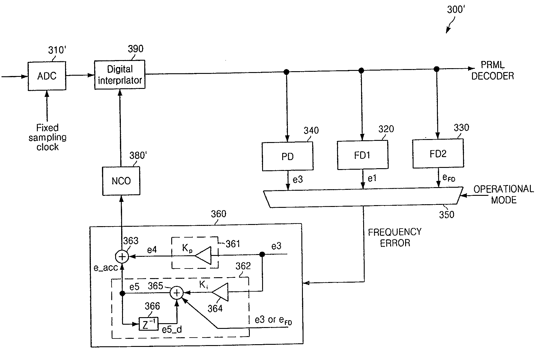
The loop filter generates an accumulated frequency error in proportion to one of the first, second, and third frequency errors that is received based upon the operational mode, wherein a locking operation with respect to the data signal is performed based upon the accumulated frequency error.

Method used


Image

  • Frequency Detector and Phase Locked Loop Having the Same
  • Frequency Detector and Phase Locked Loop Having the Same
  • Frequency Detector and Phase Locked Loop Having the Same

Examples


Embodiment Construction

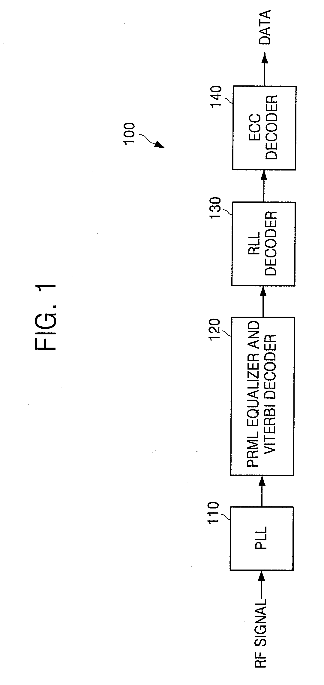
[0037]First, the operation of frequency sync and time sync will be discussed with reference to, for example, a DVD. Referring to FIG. 1, the DVD read channel includes a PLL 110, a partial response maximum likelihood (PRML) equalizer and Viterbi decoder 120, a run length limited (RLL) decoder 130, and an error correction coding (ECC) decoder 140. The PLL 100 varies the frequency of a received RF signal to a signal having a particular frequency and performs frequency sync and time sync with respect to the signal having a particular frequency. The RF signal is a signal modulated to an improved version of eight-to-fourteen modulation format (EFM+) that is a DVD format. Then, the signal output from the PLL 110 passes through the PRML equalizer and Viterbi decoder 120, the RLL decoder 130, and the ECC decoder 140 and then is restored to a data signal.

[0038]In the frequency sync operation and the time sync operation of the PLL 110, first, the PLL 110 performs frequency sync using a frequen...


PUM


Abstract

A frequency detector includes an error measurement unit measuring a time interval between zero-crossing points of an input signal that is modulated. An error conversion unit quantizes the measured time interval using one of modulation time intervals. An error calculation unit calculates a frequency error based upon a difference between the measured time interval and the quantized time interval. An error generation control unit controls whether to output the frequency error based upon the quantized time interval, the calculated frequency error, and a predetermined critical value.

Description

CROSS-REFERENCE TO RELATED APPLICATION[0001]This application claims priority to and the benefit of Korean Patent Application No. 10-2008-0054626, filed on Jun. 11, 2008, in the Korean Intellectual Property Office, the entire content of which is incorporated herein by reference.BACKGROUND[0002]1. Field of the Invention[0003]The present invention relates to a frequency detector and a phase locked loop (PLL), and, more particularly, to a frequency detector capable of continuously detecting a frequency error and a PLL capable of performing time sync using the frequency detector.[0004]2. Description of the Related Art[0005]Typically, electronic devices use a PLL to vary the frequency of a received data signal to a frequency at which the electronic devices operate and constantly maintain the frequency. The PLL performs frequency sync and time sync with respect to the received data signal.SUMMARY[0006]In accordance with exemplary embodiments of the present invention a frequency detector an...

Claims


Application Information

Patent Timeline
IPC IPC(8): H04L7/00G01R23/02H03K9/06H03L7/06H03L7/00G01R31/26G01R23/00
CPCG01R23/10G01R23/15H03L7/087H04L7/10H03L7/093H03L7/0998H04L7/0334H03L7/091H03L7/085
Inventor ZHIDKOV, SERGEYHUH, JUN HOKWON, KI SEOP
Owner SAMSUNG ELECTRONICS CO LTD
Learn More