

Frequency detection system comprising circuitry for adjusting the resonance frequency of a high temperature superconductor self-resonant coil
a high temperature superconductor and resonance frequency technology, which is applied in the direction of measuring using nmr, instruments, and magnetic field measurement using superconductive devices, etc., can solve the problems of reducing the detection ability of the detector coil distance and the associated equipment needed to operate the system
- Summary
- Abstract
- Description
- Claims
- Application Information
AI Technical Summary
Benefits of technology
Problems solved by technology
Method used
Image

Examples
examples 1-15
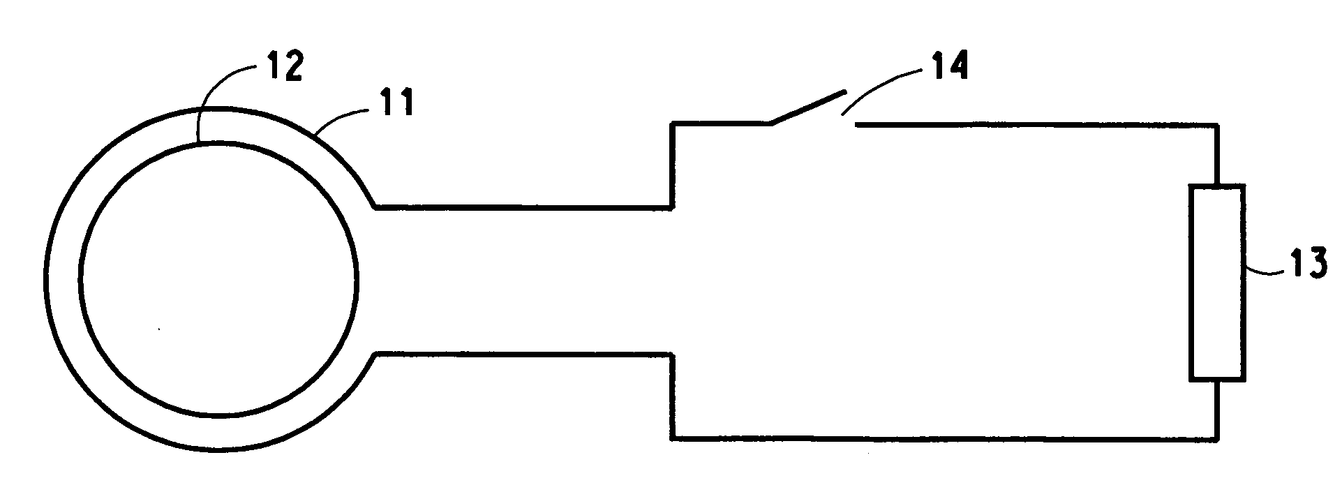
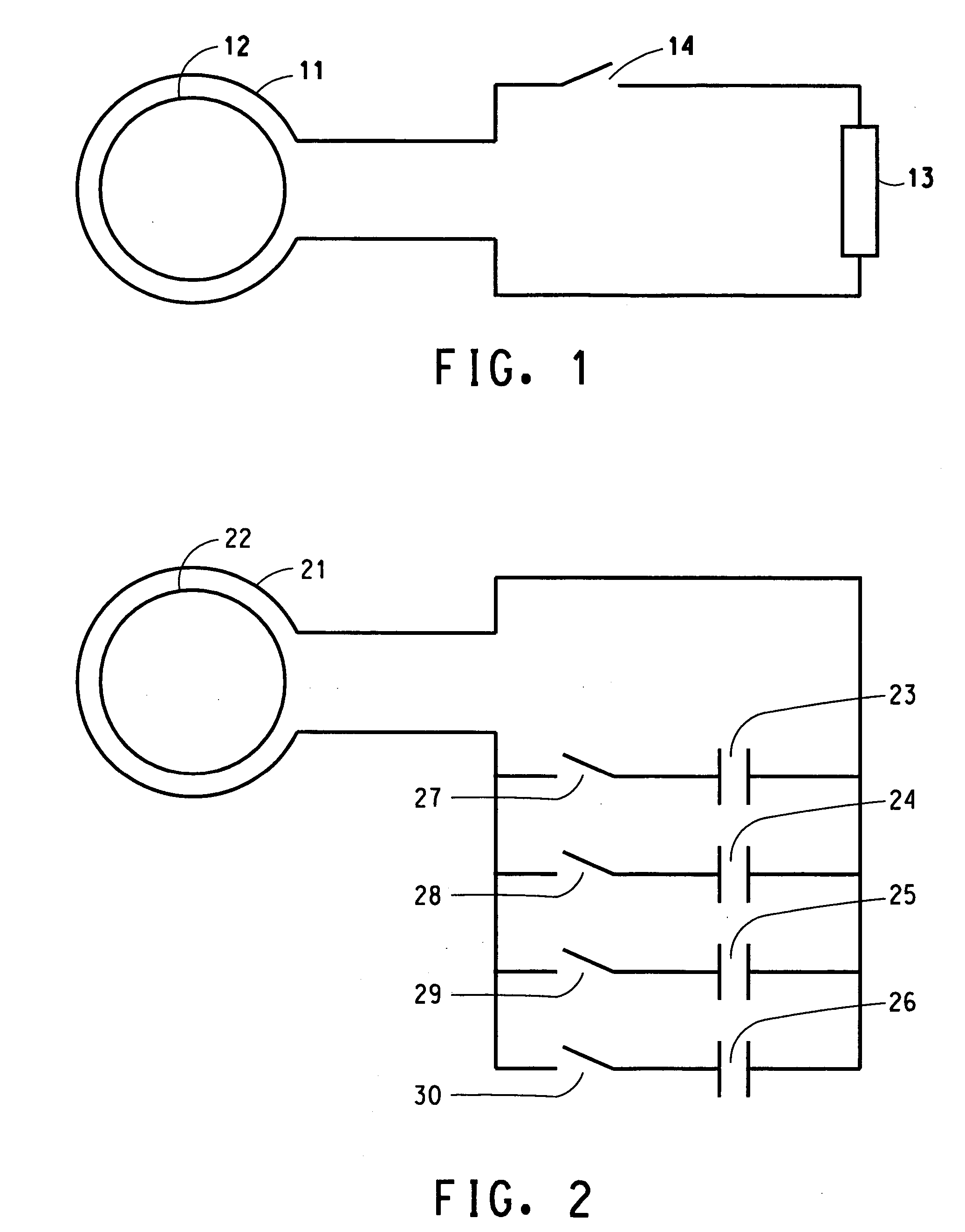
[0034] The purpose of these examples is to demonstrate the use of a circuit of the type shown in FIG. 2 to adjust the resonance frequency of a HTS self-resonant coil. The HTS self-resonant coil used is comprised of two coupled essentially identical Tl2Ba2CaCu2O8 planar coils. Each of the coupled coils is on a sapphire (Al2O3) substrate with the coil design configuration shown in FIG. 4 on both sides of the substrate.
[0035] A clean, polished single crystal sapphire substrate with a diameter of 2 inches (5.1 cm) and an approximate thickness of 0.018 inches (0.46 mm) was obtained from Union Carbide Corp. An epitaxial CeO2 buffer layer is grown on both sides of the substrate by off-axis sputter deposition with the substrate temperature held in the range of about 700-800° C. Off-axis magnetron sputtering of a Ba:Ca:Cu oxide target is used to deposit, at room temperature (about 20° C.), an amorphous precursor Ba:Ca:Cu oxide film on the CeO2 buffer layer on both sides of the substrate. Th...
examples 16-30
[0044] The purpose of these examples is to further demonstrate the use of a circuit of the type shown in FIG. 2 to adjust the resonance frequency of a HTS self-resonant coil. The HTS coil used in these examples is the same HTS self-resonant coil comprised of two coupled essentially identical Tl2Ba2CaCu2O8 planar coils used in Examples 1-15. The same holder, and the same copper single loop coupling the HTS coil to the circuit for adjusting the resonance frequency of the HTS coil as used in Examples 1-15, are used in Examples 16-30. The circuit is identical to that used in Examples 1-15 except that the capacitors 23, 24, 25 and 26 of the circuit shown in FIG. 2 had capacitances of 58, 100, 220 and 300 pF, respectively.
[0045] The resonance frequency and Q of the HTS coil is measured for each combination of capacitors connected to the single loop in the same manner as carried out for Examples 1-15. Substrate 57 has been positioned with respect to substrate 53 so that the HTS coil compr...
PUM
 Abstract
Description
Claims
Application Information