Digital filter device, phase detection device, position detection device, ad conversion device, zero cross detection device, and digital filter program

a digital filter and phase detection technology, applied in the field of digital filter devices, can solve the problems of phase difference between rising edge ed, rising edge edb>5/b> is liable to be erroneously detected, and half of a cycle error is liable to occur

Active Publication Date: 2009-12-17
TOSHIBA MASCH CO LTD
View PDF5 Cites 34 Cited by
  • Summary
  • Abstract
  • Description
  • Claims
  • Application Information

AI Technical Summary

Benefits of technology

[0026]According to the present invention, the effect of noise can be removed from the edge of a digital signal.

Problems solved by technology

In this case, when the phase difference between the rising edge Ed12 and the rising edge Ed6 should be detected, the phase difference between the rising edge Ed12 and the rising edge Ed5 is liable to be erroneously detected and an error of half of a cycle is liable to occur.

Method used


Image

  • Digital filter device, phase detection device, position detection device, ad conversion device, zero cross detection device, and digital filter program
  • Digital filter device, phase detection device, position detection device, ad conversion device, zero cross detection device, and digital filter program
  • Digital filter device, phase detection device, position detection device, ad conversion device, zero cross detection device, and digital filter program

Examples


Embodiment Construction

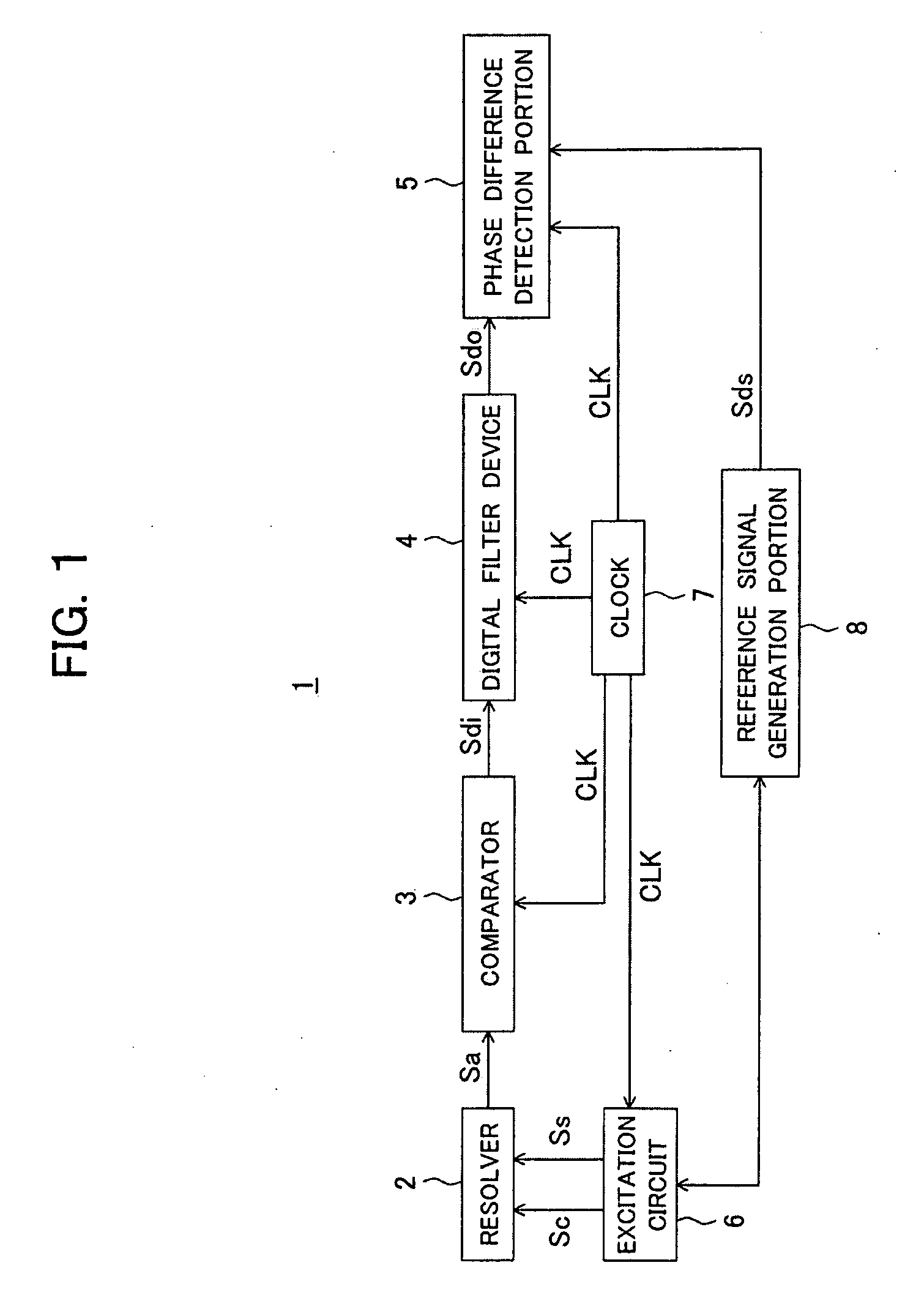
[0036]FIG. 1 is a block diagram schematically showing the overall configuration of a rotation position detection device 1 according to an embodiment of the present invention. The rotation position detection device 1 is provided with a resolver 2 attached to a motor or other detected object, a comparator 3 which performs predetermined processing with respect to an analog signal Sa from the resolver 2, a digital filter device 4, and a phase difference detection portion 5 and is configured as the device which identifies a rotation position of the detected object. The operation thereof is as follows.

[0037]The resolver 2 receives as input the two phases of analog type excitation signals Ss and Sc produced by an excitation circuit 6 based on a clock signal CLK from a clock generator. The signal levels of the excitation signals Ss and Sc respectively fluctuate by sin(ωt) and cos(ωt). The resolver 2 outputs the analog signal Sa obtained by shifting the input excitation signal Ss by exactly ...


PUM


Abstract

A digital filter device capable of removing the effect of noise such as chattering from a zero crossing signal is provided. A digital filter device 4 filtering a binary digital signal DIN and outputting a binary digital signal DOUT is provided with a toggle flip-flop 12 which switches a signal level of the digital signal DOUT each time a trigger signal is input; an XOR circuit 13 which outputs a first enable signal EN1 while a signal level of the digital signal DIN does not match with the signal level of the output digital signal DOUT; and a charge counter 14 which counts in synchronization with a clock signal CLK while the first enable signal EN1 is input and resets the count to an initial value and outputs a carry on signal ON_RCO as the trigger signal to the toggle flip-flop 12 when the count has reached an upper limit value.

Description

TECHNICAL FIELD[0001]The present invention relates to a digital filter device, a phase detection device, a position detection device, an AD conversion device, a zero cross detection device, and a digital filter program.BACKGROUND ART[0002]Binary digital signals obtained by converting analog signals output from a resolver to a digital format (RD conversion, comparate) and other digital signals representing a waveform by fluctuation of the signal level (potential etc.) contain noise due to various factors mixed in them.[0003]FIG. 7A to FIG. 7E are diagrams explaining the effects of chattering upon a zero cross of an analog signal and a digital signal. FIG. 7A is a diagram showing 1 cycle's worth of an analog signal Sga1. The abscissa indicates the time (phase), while the ordinate indicates the signal level. Further, FIG. 7B is a diagram showing a digital signal Sgd1 obtained by converting the analog signal Sga1 of FIG. 7A to a digital format. The abscissa indicates the time (phase), w...

Claims


Application Information

Patent Timeline
Patent Type & Authority Applications(United States)
IPC IPC(8): G06F17/10H03M1/12H03K3/02G01R13/02H03K5/00
CPCG01D5/24476H03M1/12H03M1/0863H03K5/1536G01D5/245G01R19/175H03K5/26H03M1/50
Inventor YOKOKAWA, NARUTOSHISATO, SHOUICHI
Owner TOSHIBA MASCH CO LTD
Why Eureka
Try Eureka