Methods and apparatus for securing optical burst switching (OBS) networks

a technology of optical burst switching and optical burst switching, applied in the field of optical networks, can solve the problems of increased capacity, serious mismatch, increased cost, etc., and achieve the effect of reducing overhead

Inactive Publication Date: 2009-12-17
THE BOARD OF RGT UNIV OF OKLAHOMA +1
View PDF11 Cites 17 Cited by
  • Summary
  • Abstract
  • Description
  • Claims
  • Application Information

AI Technical Summary

Benefits of technology

[0010]It is another object of the invention to reduce overhead associated with providing security measures to optical burst switching network.

Problems solved by technology

However, the increased capacity creates a serious mismatch with current electronic switching technologies that are designed to process individual channels within a DWDM link.
In electronic switching, the optical fiber additionally requires a photoelectric converter for converting an optical signal into an electrical signal and an electro-optic converter for converting an electrical signal into an optical signal, which results in an increased cost.
This could lead to a significant loss of statistical multiplexing efficiency when the parallel channels are used simply as a collection of independent links, rather than as a shared resource.
Optical switching technologies based on wavelength routing (circuit-switching) of a limited pool of wavelengths don't make efficient use of the transmission medium when data traffic dominates the public network.
However, a number of packet-switching operations (e.g. ultra fast pulsing, bit and packet synchronization, ultra-high-speed switching, buffering and header processing) cannot be performed optically, on a packet-by-packet basis today.
However, optical burst switching networks are vulnerable to security threats.
In OBS networks, data can be misdirected and tapped off by undesirable parties.

Method used


Image

  • Methods and apparatus for securing optical burst switching (OBS) networks
  • Methods and apparatus for securing optical burst switching (OBS) networks
  • Methods and apparatus for securing optical burst switching (OBS) networks

Examples


Embodiment Construction

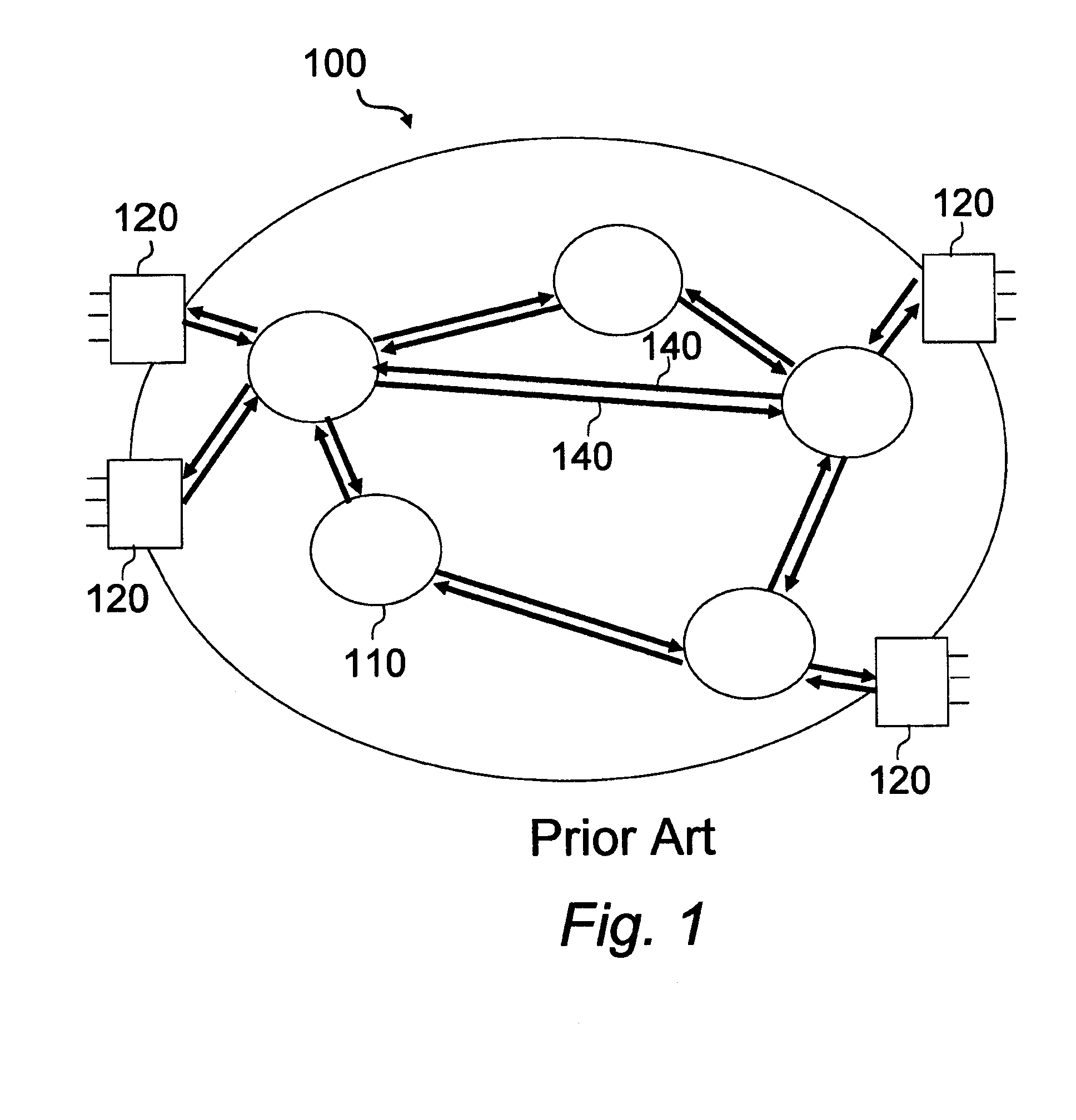
[0035]FIG. 1 shows an example of an optical burst switching network 100. The optical burst switching network 100 includes multiple electronic ingress and egress edge routers 120, and multiple optical core routers 110 connected by wavelength division multiplexing (WDM) links 140. The term WDM here includes both dense wavelength division multiplexing (DWDM) and coarse wavelength division multiplexing. The electronic ingress and egress edge routers 120 perform burst assembly and disassembly functions, and serve as legacy interfaces between the optical core routers 110 and conventional electronic routers.

[0036]As would be understood in the art, reference to a router as an ingress or egress router 120 is a relativistic term in that a single router can serve as an ingress or egress router depending on whether it is positioned at an origination point for data or a destination point for data. Similarly, a core router can be identical to an ingress or egress router in that it too can include...


PUM


Abstract

An optical network, having an optical communication link and first and second routers. The first router receives and classifies data, then forms a data burst based on destination. The first router sends an encrypted header and the data burst via the optical link. The second router, at least one hop from the first router, receives, decrypts and authenticates the header. Then, the second router extracts data burst information from the header and determines whether the address of the second router is the destination address for the data burst. If so, the second router receives the data burst and sends data to an appropriate line interface. If not, the second router selects and reserves a wavelength on a second optical link for the data burst. The second router selects an encryption key for the header, encrypts and sends the header, and then routes the data burst to the selected wavelength.

Description

CROSS-REFERENCE TO RELATED APPLICATIONS[0001]The present patent application claims priority to the provisional patent application identified by U.S. Ser. No. 61 / 055,696, filed May 23, 2008, the entire contents of which is hereby incorporated herein by reference.FIELD OF THE INVENTION[0002]The present invention relates to optical networks, and, more particularly, to systems that provide secure communications in optical networks.BACKGROUND OF THE INVENTION[0003]Over the last decade, the amount of information that is conveyed electronically has increased dramatically. As the need for greater communications bandwidth increases, the importance of efficient use of communications infrastructure increases as well. The emergence of dense-wavelength division multiplexing (DWDM) technology has improved the bandwidth problem by increasing the capacity of an optical fiber. In wavelength division multiplexing, channels are arranged by a predetermined wavelength interval, and signals are loaded on...

Claims


Application Information

Patent Timeline
Patent Type & Authority Applications(United States)
IPC IPC(8): H04L9/32H04L29/06H04L9/08
CPCH04L63/0428H04L63/061H04L9/0827H04Q11/0066H04Q2011/0079H04L63/162
Inventor VERMA, PRAMODE K.CHEN, YUHUA
Owner THE BOARD OF RGT UNIV OF OKLAHOMA
Why Eureka
Try Eureka