Method for producing pearlitic rail excellent in wear resistance and ductility

a technology of pearlite rail and wear resistance, which is applied in the direction of shaping tools, furnaces, heat treatment apparatuses, etc., can solve the problems of increased ductility and toughness decline, increased ductility and toughness, and experience brittle fracture, etc., to improve ductility and toughness, and improve the quality of pearlite. , the effect of excellent wear resistan

Active Publication Date: 2009-12-24
NIPPON STEEL CORP
View PDF101 Cites 19 Cited by
  • Summary
  • Abstract
  • Description
  • Claims
  • Application Information

AI Technical Summary

Benefits of technology

[0018]Against this backdrop, it is desirable to provide a pearlitic rail having improved du

Problems solved by technology

Although high carbon pearlitic steel is used as a railway rail material because of its excellent wear resistance, it is inferior in ductility and toughness owing to very high carbon content.
When such a rail is used at low temperature such as in a cold-climate region, it experiences brittle fracture starting from small initial defects and fatigue cracks.
In recent years, moreover, efforts to improve the wear resistance of rail steel by increasing carbon content to still higher levels have led to additional declines in ductility and toughness.
However, the degree to which hot rolling temperature can be lowered and reduction increased during rail production is limited by the need to maintain formability during hot rolling.
Thorough refinement of austenite grains is therefore impossible.
Further, thorough pearlite structure refinement cannot be achieved by using transformation nuclei to transform pearlite from within the austenite grains, because it is difficult to control the abundance of the transformation nuclei and the transformation of pearlite from within the grains is not stable.
However, when the aforesaid low-temperature reheating heat treatment is applied to

Method used


Image

  • Method for producing pearlitic rail excellent in wear resistance and ductility
  • Method for producing pearlitic rail excellent in wear resistance and ductility
  • Method for producing pearlitic rail excellent in wear resistance and ductility

Examples


examples

[0118]Examples of the present invention are explained in the following.

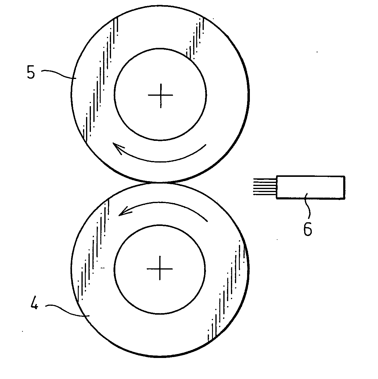
[0119]The chemical compositions of test rail steels are shown in Table 1. Table 2 shows the finish hot rolling conditions, reaction force ratios, head residual ratios of unrecrystallized austenite structure immediately after hot rolling, and heat treatment conditions when using the test steels shown in Table 1 (Steels: A to J, O and P) to carry out production by the invention rail production method. Table 3 shows the microstructures and hardnesses at 2 mm under the rail head surface of the rails produced under the conditions of Table 2, the total elongations in tensile testing of test pieces thereof taken at the location shown in FIG. 4, and the results of wear testing conducted by the method shown in FIG. 6 on test pieces thereof taken at the location shown in FIG. 5. The numerical values in FIGS. 4 and 5 are expressed in millimeters (mm) In FIG. 6, the reference numerals 4, 5 and 6 designate a rail test piece, ...


PUM

PropertyMeasurementUnit
Temperatureaaaaaaaaaa

Abstract

The invention provides a method for producing a pearlitic rail by subjecting to at least rough hot rolling and finish hot rolling a billet comprising, in mass %, C: 0.65-1.20%, Si: 0.05-2.00%, Mn: 0.05-2.00%, and a remainder of iron an unavoidable impurities, wherein the finish hot rolling is conducted by rolling at a rail head surface temperature in a range of not higher than 900° C. to not lower than Ar3 transformation point or Arcm transformation point to produce a head cumulative reduction of area of not less than 20% and a reaction force ratio of not less than 1.25, and the finish hot rolled rail head surface is subjected to accelerated cooling or spontaneous cooling to at least 550° C. at a cooling rate of 2 to 30° C./sec, thereby refining the rail head structure to attain a hardness within a predetermined range and improving rail wear resistance and ductility.

Description

FIELD OF THE INVENTION[0001]This invention relates to a method for producing a rail for use in heavy haul railways, particularly to a pearlitic rail production method directed to simultaneously improving wear resistance and ductility of the rail head.DESCRIPTION OF THE RELATED ART[0002]Although high carbon pearlitic steel is used as a railway rail material because of its excellent wear resistance, it is inferior in ductility and toughness owing to very high carbon content.[0003]For example, the ordinary carbon steel rail of a carbon content of 0.6 to 0.7 mass % according to JIS E1101-1990 has a normal temperature impact value by the JIS No. 3 U-notch Charpy test of around 12 to 18 J / cm2. When such a rail is used at low temperature such as in a cold-climate region, it experiences brittle fracture starting from small initial defects and fatigue cracks.[0004]In recent years, moreover, efforts to improve the wear resistance of rail steel by increasing carbon content to still higher leve...

Claims


Application Information

Patent Timeline
IPC IPC(8): B21D31/00
CPCB21B1/085C21D8/0205C22C38/04C21D2211/009C22C38/02C21D9/04
Inventor UEDA, MASAHARUSEKI, KAZUNORISATO, TAKUYAYAMAMOTO, TAKESHI
Owner NIPPON STEEL CORP
Why Eureka
Try Eureka