Detection of faults in an injector arrangement

a fuel injector and fault detection technology, which is applied in the direction of engine testing, structural/machine measurement, electrical control, etc., can solve the problems of catastrophic engine failure, failure of drive circuit, and previously unidentifiable individual faulty injectors, and achieve robust results.

Inactive Publication Date: 2009-12-24
DELPHI INT OPERATIONS LUXEMBOURG S A R L
View PDF16 Cites 28 Cited by
  • Summary
  • Abstract
  • Description
  • Claims
  • Application Information

AI Technical Summary

Benefits of technology

[0034]The calibration of the top rail voltage, the delay period, the threshold short circuit resistance, and the predetermined voltage drop limit is important to ensure accurate results from these diagn

Problems solved by technology

Like any circuit, faults may occur in a drive circuit.
In safety critical systems, such as diesel engine fuel injection systems, a fault in the drive circuit may lead to a failure of the injection system, which could consequentially result in a catastrophic failure of the engine.
However, it has previously not been possible to identify individual faulty injectors 12 that are short circuit, because of the risk of ‘charge sharing’ between faulty and non-faulty injectors.
An other problem associated with charge sharing is the risk that an uncontrolled injection could occur.
If a low resistance short circuit were to occur it is possible that the faulty injector could fully discharge in a very short period of time.
In so-called ‘discharge to inject’ systems, this results in the injector valve needle 17 lifting relative to the valve

Method used


Image

  • Detection of faults in an injector arrangement
  • Detection of faults in an injector arrangement
  • Detection of faults in an injector arrangement

Examples


Embodiment Construction

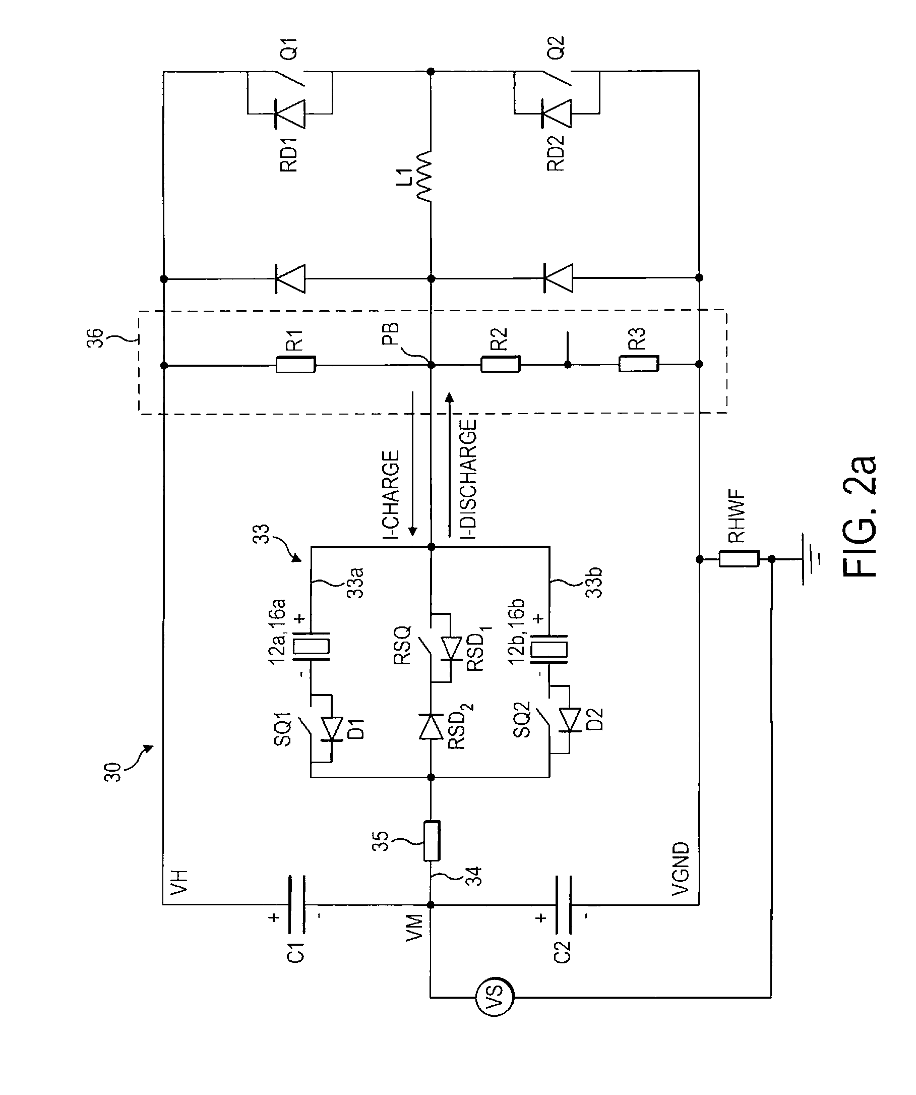
[0063]Referring to FIG. 2a, this shows an injector drive circuit 30 according to the present invention. The injector drive circuit 30 comprises an injector bank circuit 33, in which a pair of piezoelectric injectors 12a, 12b are connected. It should be appreciated that although the respective injectors 12a, 12b are shown as integral to the injector bank circuit 33 in FIG. 2a, in practice the injector bank circuit 33 would be remote from the injectors 12a, 12b and connected thereto by way of power supply leads.

[0064]The drive circuit 30 includes three voltage rails: a high voltage rail VH (typically 255 V), a mid voltage rail VM (typically 55 V), and a ground voltage rail VGND (i.e. 0 V). The drive circuit 30 is generally configured as a half H-bridge with the mid voltage rail VM serving as a bi-directional middle current path 34. The injector bank circuit 33 is located in the middle current path 34 of the drive circuit 30 and comprises a pair of parallel branches 33a, 33b in which t...


PUM


Abstract

A method of identifying an individual short circuit fuel injector, within an injector bank of an engine comprising a plurality of fuel injectors. Each fuel injector has a piezoelectric actuator and an associated injector select switch forming part of an injector drive circuit. The method comprises: (i) charging all of the piezoelectric actuators of the plurality of fuel injectors within the injector bank during a charge phase; (ii) at the end of the charge phase waiting for a delay period; and (iii) subsequently closing an injector select switch of a fuel injector to select said fuel injector. The method further comprises: (iv) determining a stack voltage present on terminals of the piezoelectric actuator of the selected fuel injector and storing the stack voltage in a data store. The stack voltage is indicative of an amount of charge present on the selected injector at the end of the delay period. The method further comprises (v) repeating steps (i) to (iv) for each fuel injector in the injector bank in turn; and (vi) identifying the individual short circuit fuel injector as being the injector which has discharged beyond a predetermined voltage drop limit during the delay period. The method also comprises generating a short circuit fault signal for the identified fuel injector.

Description

TECHNICAL FIELD[0001]The present invention relates to a method and apparatus for detecting faults in a fuel injector arrangement, and particularly to a method and apparatus for detecting short circuit faults in piezoelectric fuel injectors.BACKGROUND TO THE INVENTION[0002]In a direct injection internal combustion engine, a fuel injector is provided to deliver a charge of fuel to a combustion chamber prior to ignition. Typically, the fuel injector is mounted in a cylinder head with respect to the combustion chamber such that its tip protrudes slightly into the chamber in order to deliver a charge of fuel into the chamber.[0003]One type of fuel injector that is particularly suited for use in a direct injection engine is a so-called piezoelectric injector. A piezoelectric injector 12 and its associated control system 24 are shown schematically in FIG. 1.[0004]The piezoelectric injector 12 includes a piezoelectric actuator 16 that is operable to control the position of an injector valve...

Claims


Application Information

Patent Timeline
IPC IPC(8): G01M15/04
CPCF02D41/2096F02D41/221F02D2041/2051F02M2200/21F02D2041/2072F02D2041/2082F02D2041/2093F02D2041/2058
Inventor PERRYMAN, LOUISA J.HOPLEY, DANIEL JEREMY
Owner DELPHI INT OPERATIONS LUXEMBOURG S A R L
Why Eureka
Try Eureka