Flat plate heat and moisture exchanger

a technology of heat and moisture exchanger and flat plate, which is applied in the direction of air heaters, lighting and heating equipment, electrochemical generators, etc., can solve the problems of limited airtight home natural ventilation, health problems, mold growth and structural damage, etc., and achieve the effect of convenient manufacturing and operation efficiency

Active Publication Date: 2009-12-24
ZEHNDER VERKAUFS UND VERW
View PDF5 Cites 67 Cited by
  • Summary
  • Abstract
  • Description
  • Claims
  • Application Information

AI Technical Summary

Benefits of technology

[0021]Accordingly, it is an object of the invention to provide an improved ERV core which can be easily manufactured, meets the UL900 Class

Problems solved by technology

However, unless properly ventilated, an airtight home can seal in indoor air pollutants and/or moisture.
Contaminants such as formaldehyde, volatile organic compounds, and radon can accumulate in poorly ventilated homes, causing health problems.
Excess moisture in a home can generate high humidity levels which can lead to mold growth and structural damage.
In a modern airtight home natural ventilation is limited;(b) Whole-structure ventilation which provides controlled air movement using one or more fans and duct systems.
Cu

Method used


Image

  • Flat plate heat and moisture exchanger
  • Flat plate heat and moisture exchanger
  • Flat plate heat and moisture exchanger

Examples


Embodiment Construction

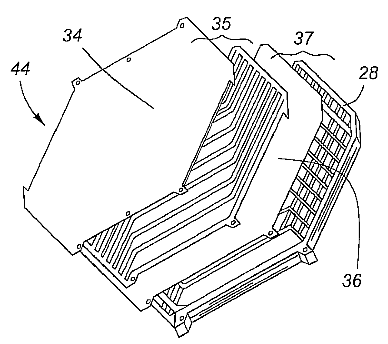
[0042]In general, the invention provides an ERV cross flow plate core which allows two air streams to flow in close proximity to one another and transfer heat / moisture through a membrane separating the two air streams. The ERV core consists of left and right hand flat spacers with membranes laminated thereto to form wafers which are stacked together to form the core.

[0043]Referring to FIGS. 3A and 3B, a top and side view respectively of a left hand spacer 22 in accordance with the present invention is depicted. Each left hand spacer 22 is generally hexagonal in shape and includes a series of parallel curvilinear arms 24 to form channels 26, which as will be explained below, serve to direct a first air stream moving through the ERV core. A membrane 34 (see FIG. 5) is bonded to the top of the left hand spacer 22 and trimmed to the shape of left hand spacer 22. The left hand spacer 22 with bonded membrane 34 forms a left hand wafer 35.

[0044]FIG. 4 depicts aright hand spacer 28. Similar...


PUM

PropertyMeasurementUnit
Angleaaaaaaaaaa
Digital informationaaaaaaaaaa
Melting pointaaaaaaaaaa

Abstract

This invention relates in general to air exchange systems and, in particular, to an improved energy recovery ventilator, a cross flow plate core associated therewith and a method of conditioning air for a building. In one aspect, the invention provides a cross flow plate core comprising: a left hand wafer comprising a left hand spacer with a first of a plurality of membranes bonded thereto, the left hand spacer comprising a plurality of parallel curvilinear rails which form channels for receiving a first stream of air; and a right hand wafer comprising a right hand spacer with a second of the plurality of membranes bonded thereto, the right hand spacer comprising a plurality of parallel curvilinear rails which form channels for receiving a second stream of air, wherein the left hand spacer of the left hand wafer is bonded to the top of the membrane of the right hand wafer.

Description

BACKGROUND OF THE INVENTION[0001]1. Field of the Invention[0002]This invention relates in general to air exchange systems and, in particular, to an improved energy recovery ventilator (ERV), a cross flow plate core associated therewith and a method of conditioning air for a building.[0003]2. Description of the Prior Art[0004]Modern construction of commercial or residential buildings focuses on energy efficient building techniques which create airtight structures to minimize, in particular, heat loss in the winter and to reduce air conditioner use in the summer. However, unless properly ventilated, an airtight home can seal in indoor air pollutants and / or moisture. Contaminants such as formaldehyde, volatile organic compounds, and radon can accumulate in poorly ventilated homes, causing health problems. Excess moisture in a home can generate high humidity levels which can lead to mold growth and structural damage. Heating, ventilation and air conditioning (HVAC) systems in modern hom...

Claims


Application Information

Patent Timeline
IPC IPC(8): F28F9/02F25D17/04F24H3/02H01M8/10
CPCF24F3/1411F24F12/006F28D9/0068F28F21/065Y02B30/563H01M8/04007H01M8/04074H01M8/04119Y02E60/50F28F2245/02Y02B30/56
Inventor GRINBERGS, PETER KARLKWAN, WILLIAM
Owner ZEHNDER VERKAUFS UND VERW
Why Eureka
Try Eureka