Motor

a technology of motors and housing holes, applied in the direction of dynamo-electric machines, magnetic circuit rotating parts, magnetic circuit shapes/forms/construction, etc., can solve the problems of permanent magnet falling out, end surface plate loosening and coming off in the axial direction, end surface plate rotating in the circumferential direction, etc., to prevent permanent magnet from falling out from the housing hole and improve the cooling performance of the motor.

Inactive Publication Date: 2009-12-24
HONDA MOTOR CO LTD
View PDF10 Cites 42 Cited by
  • Summary
  • Abstract
  • Description
  • Claims
  • Application Information

AI Technical Summary

Benefits of technology

[0058]In this case, the ring-shaped plate is pressed toward the rotor yoke by the restoring force of the flexurally deformed supporting plate, and it is therefore possible to reliably prevent the permanent magnet from falling out from the housing hole. Also in this case, between the rotor yoke and the supporting plate, there is formed a groove section with the inner circumferential surface of the ring-shaped plate serving as its bottom surface, and consequently it is possible to improve cooling performance of the motor.

Problems solved by technology

Incidentally, a problem with the end surface plate according to the above Patent Document 1 is how to fasten the end surface plate and the shaft.
Therefore, in a case where the motor becomes a high temperature when driving the motor, a clearance occurs between the end surface plate and the shaft, with the possibility that the end surface plate becomes loosened and comes off in the axial direction.
As a result, a clearance occurs between the end surface plate and the rotor yoke, with the possibility of the permanent magnet falling out.
However, as mentioned above, in a case where the end surface plate becomes loosened due to the difference in coefficient of linear expansion between the end surface plate and the shaft, there is a problem in that the end surface plate rotates in the circumferential direction.
However, there is a problem with this configuration in that there is an additional cost increase for providing the rotation detent, and since the plate thickness of the collar needs to be ensured to some extent, the weight of the motor increases.

Method used


Image

  • Motor
  • Motor
  • Motor

Examples


first embodiment

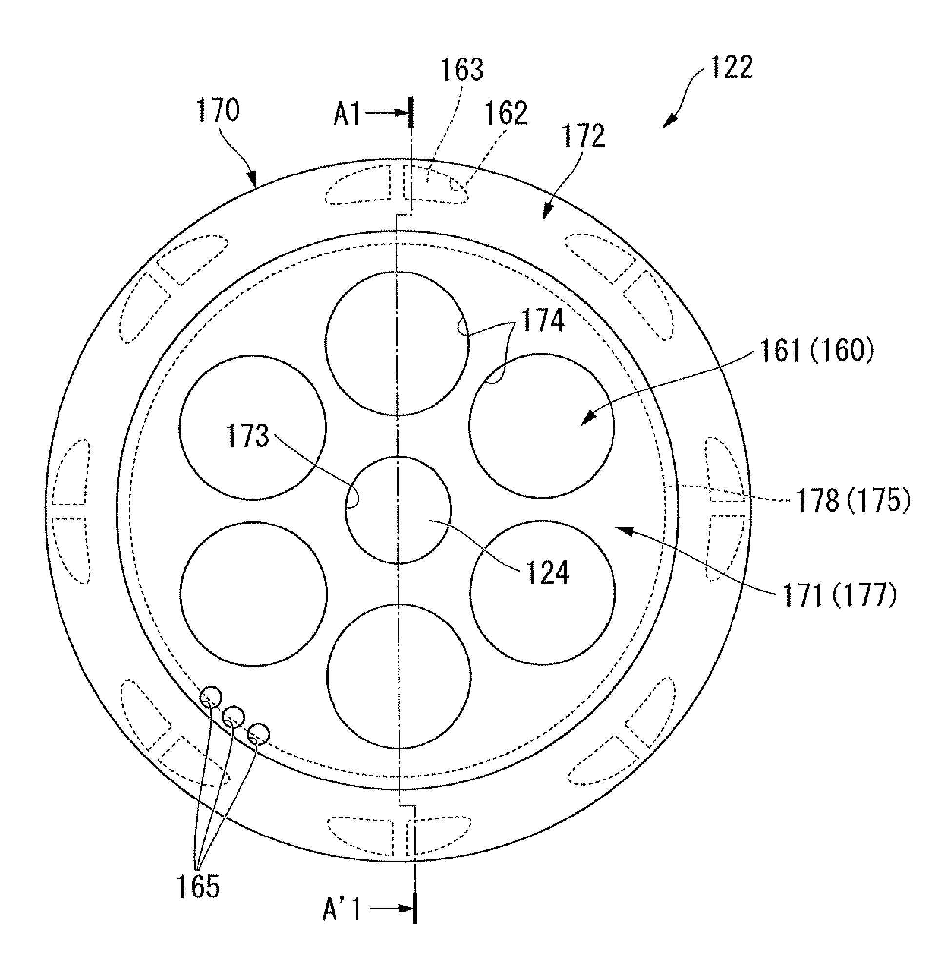
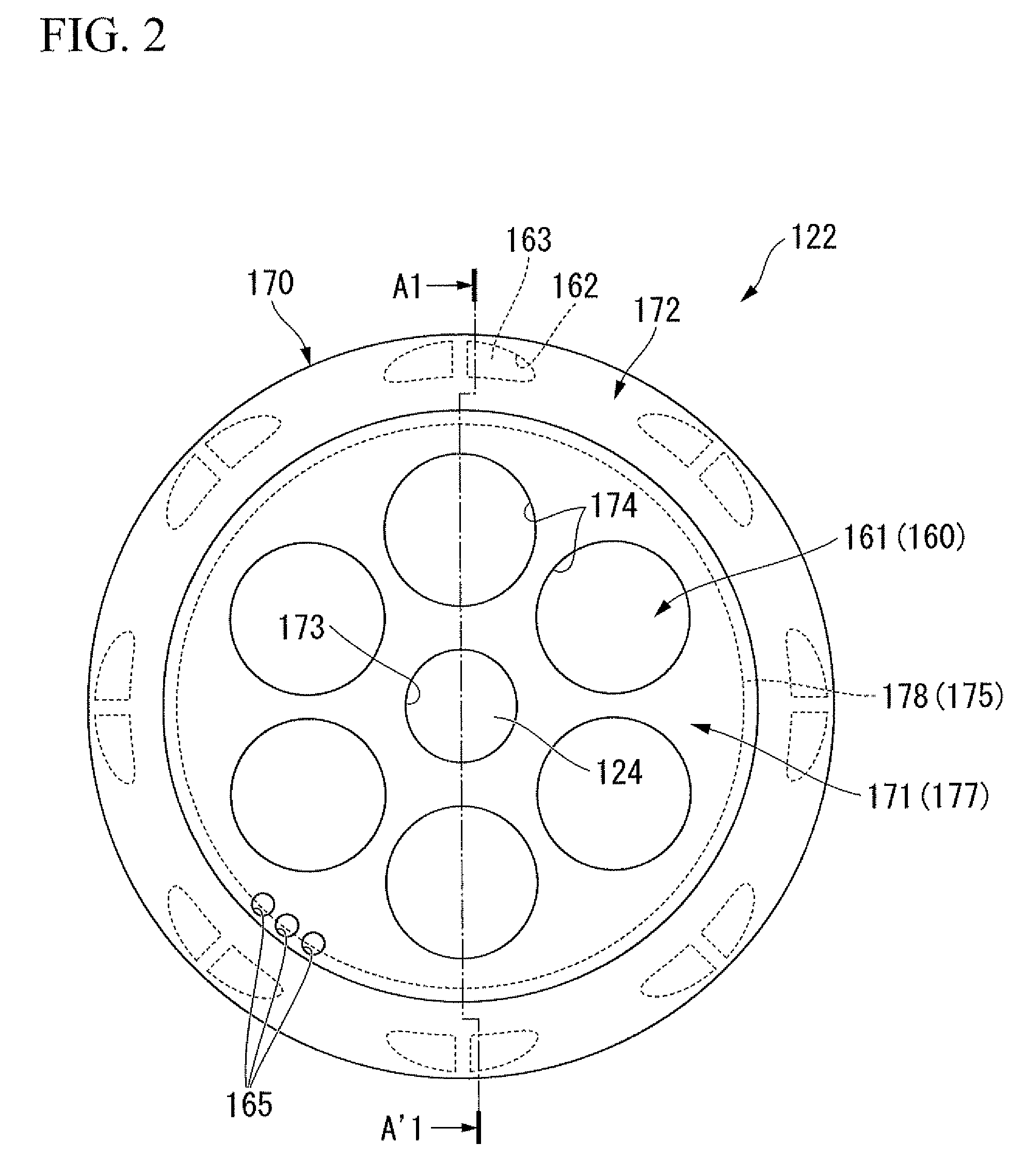
[0093]FIG. 2 is a side view of the rotor section, and FIG. 3 is a sectional view taken along the line A1-A′1 of FIG. 2.

[0094]As shown in FIG. 2 and FIG. 3, the rotor section 122 is arranged on the inner side of the above-mentioned stator 121 with a predetermined clearance therebetween. The rotor section 122 is provided with a rotor yoke 161 that is press-fitted and fixed on the output shaft 124. The rotor yoke 161 is formed with magnetic plate materials 160 laminated along the axial direction of the output shaft 124, and in the periphery portion of an end surface 161a thereof, there are formed a plurality of (for example, sixteen) housing holes 162 passing through in the axial direction of the rotor yoke 161. These housing holes 162, on the periphery portion of the end surface 161a of the rotor yoke 161, are arranged around the circumferential direction at equal intervals, and are of an arc shape or rectangular shape in plan view. In each of the housing holes 162 there is inserted a...

second embodiment

[0114]Next, a second embodiment of the present invention is described. In the following description, parts having a similar structure to those in the above first embodiment are denoted by the same reference symbols and detailed descriptions thereof are omitted.

[0115]FIG. 4 is a sectional view of a rotor section according to the second embodiment of the present invention.

[0116]As shown in FIG. 4, an end surface plate 1170 of the present embodiment is such that instead of the lightening holes 174 (refer to FIG. 3) of the end plate 171 in the above-mentioned first embodiment, between the inner periphery portion and the outer periphery portion of the end plate 1171, there is formed a thin wall section 1100 that is thinner than the thickness of the inner periphery portion and the outer periphery portion.

[0117]The thin wall section 1100 is formed between the small-diameter section of the end plate 1171, that is, the press-fitting hole 173 of the end plate 1171, and the center hole 176 of ...

third embodiment

[0126]Next, a third embodiment of the present invention is described, with reference to the accompanying drawings. In the present embodiment, there is described a motor employed for a drive motor unit for a vehicle.

[0127](Drive Motor Unit for a Vehicle)

[0128]FIG. 7 is a schematic configuration sectional view of the drive motor unit for a vehicle.

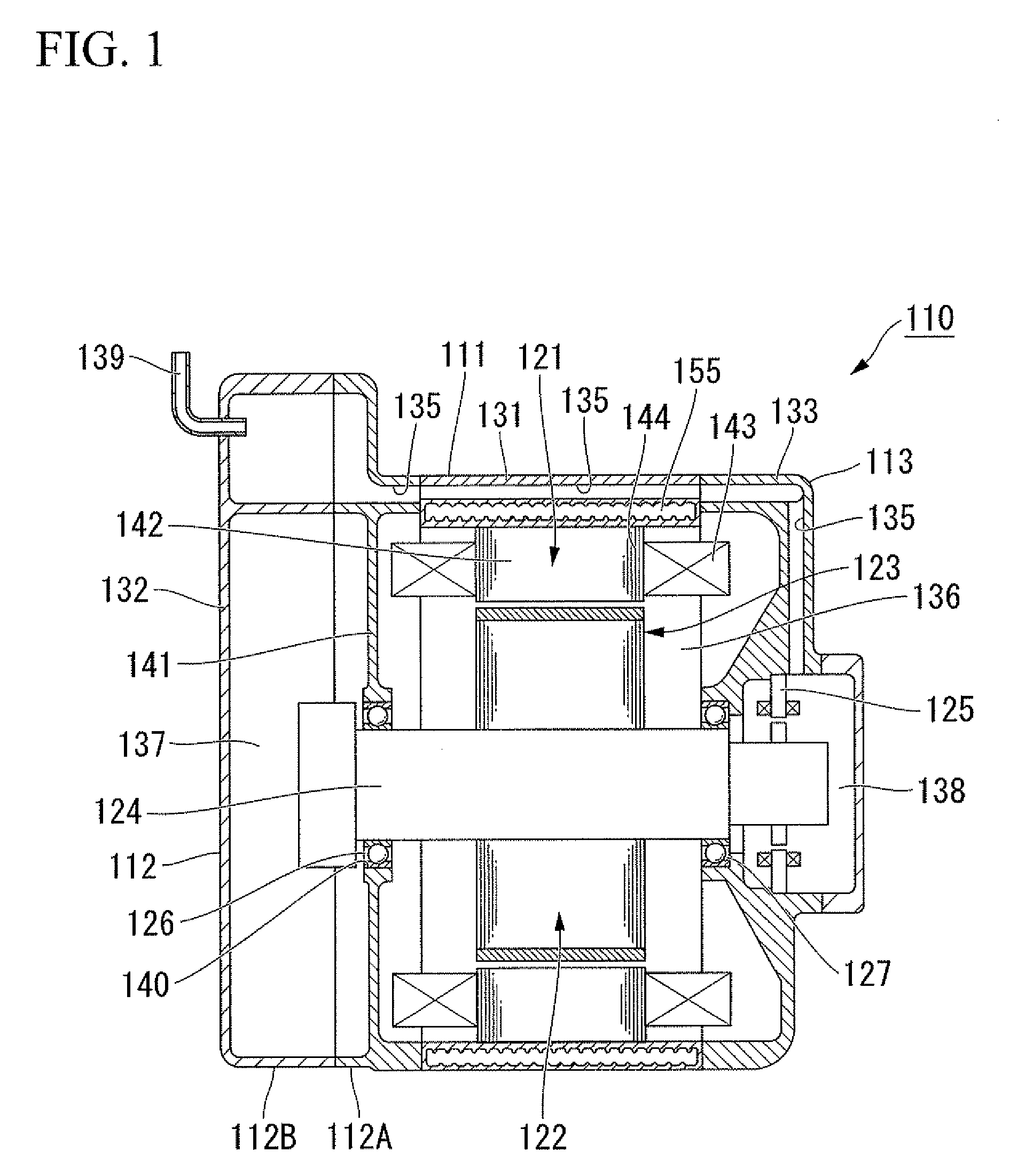
[0129]As shown in FIG. 7, the drive motor unit for a vehicle (hereunder, referred to as motor unit) 210 is provided with: a motor housing 211 that houses a motor 223 provided with a stator section 221 and a rotor section 222; a transmission housing 212 that is fastened onto one axial side of the motor housing 211 and that houses a power transmission section (not shown in the drawing) that transmits power from an output shaft (shaft) 224 (made of iron for example) of the motor 223; and a sensor housing 213 that is fastened onto the other axial side of the motor housing 211 and that houses a rotation sensor 225 of the motor 223. The transmissi...


PUM


Abstract

A motor including: a rotatably supported shaft; and a rotor section press-fitted and fixed coaxially to the shaft, wherein the rotor section is provided with: a rotor yoke; a housing hole formed on an end surface of the rotor yoke along the axial direction of the shaft; a permanent magnet housed within the housing hole; and a pair of end surface plates: that have a ring-shaped plate that is provided so as to cover at least an opening section of the housing hole and that is made of a non-magnetic material, and a supporting plate that supports the ring-shaped plate, that is press-fitted and fixed on the shaft, and that has a coefficient of linear expansion equivalent to that of the shaft; that are provided on axial end portions of the rotor yoke; and that clamp the rotor yoke so as to hold the permanent magnet within the housing hole.

Description

BACKGROUND OF THE INVENTION[0001]Priority is claimed on Japanese Patent Application No. 2008-159221, filed Jun. 18, 2008, Japanese Patent Application No. 2008-159557, filed Jun. 18, 2008, and Japanese Patent Application No. 2008-160125, filed Jun. 19, 2008, the contents of which are incorporated herein by reference.FIELD OF THE INVENTION[0002]The present invention relates to a motor.DESCRIPTION OF THE RELATED ART[0003]Heretofore, there has been known a motor that is provided with a cylinder-shaped stator, a rotor section that is arranged on the inner side of the stator, and a shaft that is press-fitted and fixed coaxially to the rotor and that is rotatably supported. Motors are widely used as a power source in various areas such as home electric appliance products, and are also used in recent years as a power source for vehicles such as hybrid vehicles and fuel cell vehicles.[0004]The rotor section of the motor mentioned above is provided with: a rotor yoke with a plurality of magne...

Claims


Application Information

Patent Timeline
Patent Type & Authority Applications(United States)
IPC IPC(8): H02K1/28
CPCH02K1/28H02K1/276
Inventor SUZUKI, TAKANORIFUKUSHIMA, TATSUYA
Owner HONDA MOTOR CO LTD
Why Eureka
Try Eureka