
High sensitivity frequency modulated radar level gauge system

a radar level gauge and high sensitivity technology, applied in the field of frequency modulated can solve the problems of insufficient level of sensitivity of current radar level gauge systems, and achieve the effect of increasing sensitivity

Active Publication Date: 2009-12-24
ROSEMOUNT TANK RADAR
View PDF11 Cites 20 Cited by
  • Summary
  • Abstract
  • Description
  • Claims
  • Application Information

AI Technical Summary

Benefits of technology

[0008]In view of the above-mentioned and other drawbacks of the prior art, a general object of the present invention is to provide an improved frequency modulated radar level gauge system, and in particular a frequency modulated radar level gauge system having an increased sensitivity.
[0016]The present invention is based upon the realization that an improved sensitivity can be achieved by improving the signal isolation in the radar level gauge system. In particular, the present inventor has realized that the signal isolation should be improved, that is, the leakage between the transmitter branch and the receiver branch should be reduced, for electromagnetic signals within the frequency range of the received echo signals (and thus the transmitted electromagnetic signals).
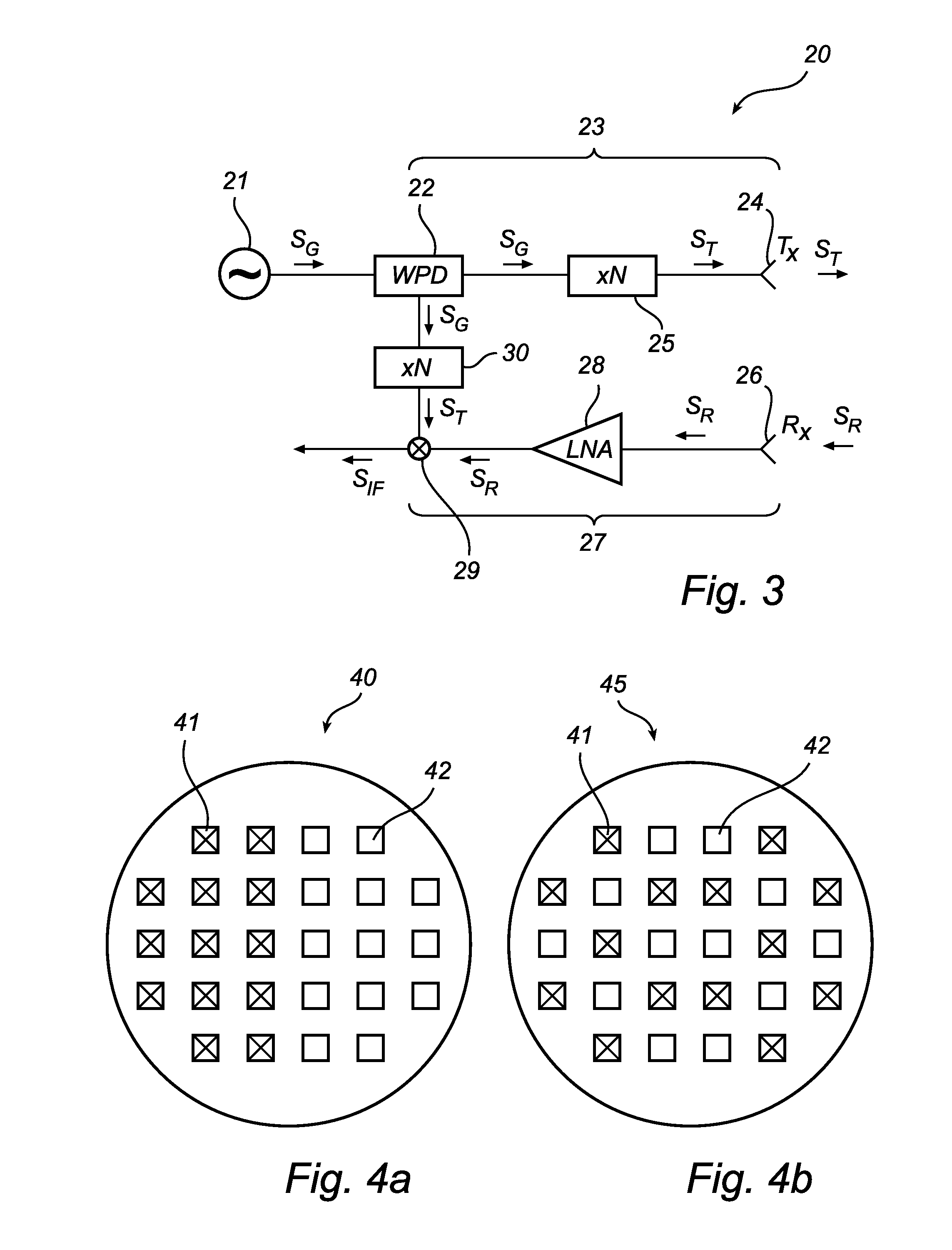
[0017]By providing, in the transceiver, first and second frequency converters in accordance with the present invention, the number of leakage paths for electromagnetic signals within the frequency range of the transmitted and received electromagnetic signals can be reduced significantly, because, apart from along the receiver branch, such signals only exist between the first frequency converter and the transmitting propagating device and between the second frequency converter and the mixer. Through suitable positioning of the first and second frequency converters, that is, as close as possible to the transmitting propagating device and the mixer, respectively, the number of relevant leakage paths can be reduced considerably. Accordingly, the signal isolation between the transmitter and receiver branches can be significantly reduced and, hence, the sensitivity of the radar level gauge system increased.
[0018]To even further increase the sensitivity of the radar level gauge system according to the present invention, a signal isolation between the transmitting propagating device and the receiving propagating device may be at least 30 dB. With an even further increased signal isolation between the transmitting propagating device and the receiving propagating device of, say, 50 dB, a frequency-modulated radar level gauge system can be achieved in which the measurement sensitivity is not limited by the signal isolation, but rather by noise. When such a level has been reached, further measures can be taken to increase the signal-to-noise ratio. Such measures may, for example, include amplifying the received echo signals using a low noise amplifier, increasing the power of the transmitted electromagnetic signals etc.
[0023]By providing the dual-function structure as a patch antenna, a compact and low-cost antenna solution can be achieved.
[0024]According to one embodiment, the transmitter supporting element and the receiver supporting element may be provided as separate elements, whereby a very high signal isolation between the transmitter part and the receiver part can be achieved.

Problems solved by technology

In view of demanding applications such as those exemplified above, currently available radar level gauge systems often exhibit an insufficient level of sensitivity.

Method used


Image

  • High sensitivity frequency modulated radar level gauge system
  • High sensitivity frequency modulated radar level gauge system
  • High sensitivity frequency modulated radar level gauge system

Examples


Embodiment Construction

[0035]In the present description, embodiments of the present invention are mainly described with reference to a radar level gauge system of the frequency modulated continuous wave (FMCW) type having a single patch antenna for radiating and capturing electromagnetic signals. It should be noted that this by no means limits the scope of the invention, which is equally applicable to other frequency-modulated radar level gauge systems, such as RLG-systems in which pulses modulated on a carrier are used for filling level determination.

[0036]Moreover, the radar level gauge system according to the present invention may be equipped with any other type of propagating device(s), such as a horn antenna, a rod antenna, an array antenna, or a probe, such as a single-line probe (including a so-called Goubau probe), a twin-line probe or a coaxial probe.

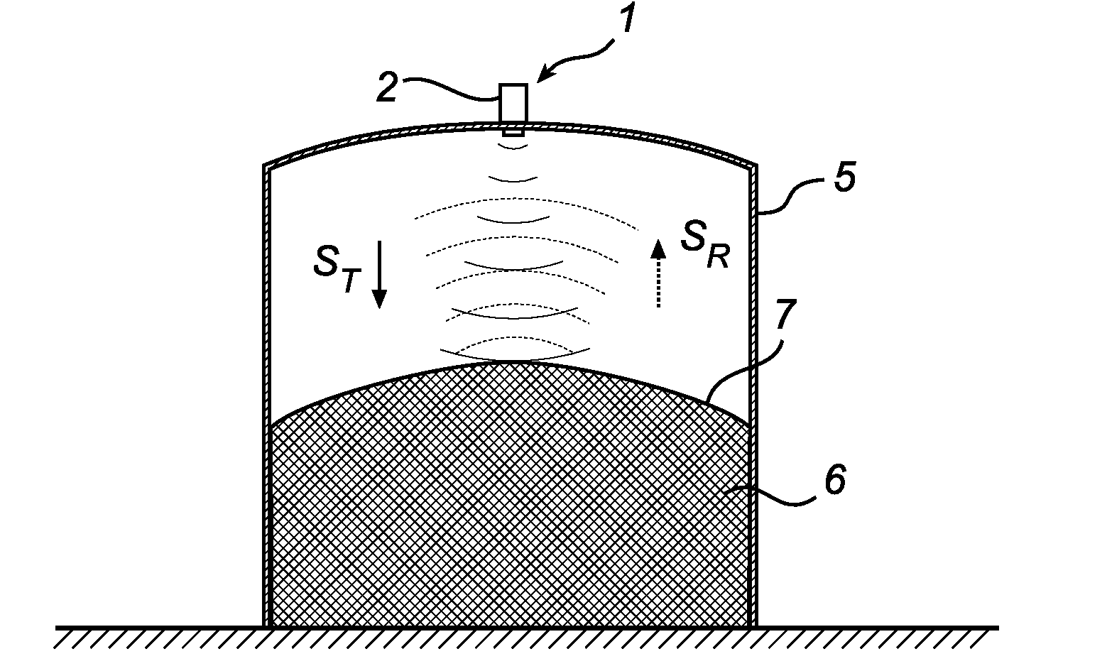
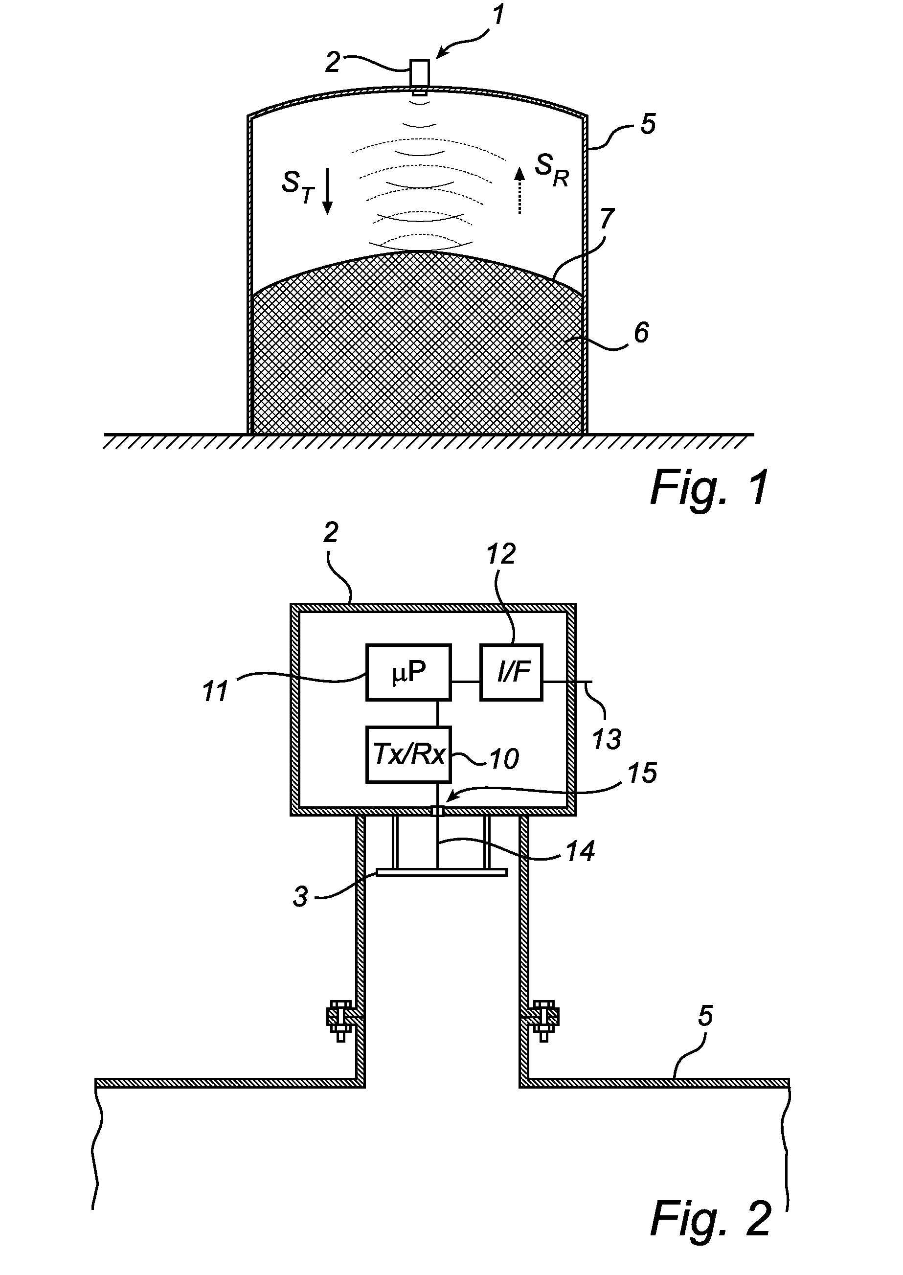
[0037]FIG. 1 schematically illustrates a radar level gauge system 1 according to an embodiment of the present invention, comprising a measurement el...


PUM


Abstract

A radar level gauge system for determining a filling level of a product contained in a tank, comprising: a transceiver for generating, transmitting and receiving frequency-modulated electromagnetic signals; a transmitting propagating device electrically connected to the transceiver and arranged to propagate transmitted electromagnetic signals towards a surface of the product contained in the tank; and a receiving propagating device electrically connected to the transceiver and arranged to return echo signals resulting from reflections at impedance transitions encountered by the transmitted electromagnetic signals, including a surface echo signal resulting from reflection at the surface, back to the transceiver. A signal isolation between the transmitting propagating device and the receiving propagating device is at least 30 dB, and the transceiver comprises: a signal generator for generating a frequency-modulated signal having a predetermined center frequency; a transmitter branch connecting an output of the signal generator with the transmitting propagating device via a first frequency converter for converting the frequency of the frequency-modulated signal to provide the transmitted electromagnetic signal; a receiver branch connected to the receiving propagating device for receiving the surface echo signal; and a mixer having a first input connected to the signal generator via a second frequency converter for converting the frequency of the frequency-modulated signal and a second input connected to the receiver branch, for forming an intermediate frequency signal indicative of a phase difference between the transmitted electromagnetic signal and the surface echo signal. The radar level gauge system further comprising processing circuitry connected to the transceiver for determining the filling level based on the intermediate frequency signal.

Description

TECHNICAL FIELD OF THE INVENTION[0001]The present invention relates to a frequency modulated radar level gauge system.TECHNICAL BACKGROUND[0002]Radar level gauge systems are today in use in a variety of fields of application for accurate filling level determination. For determining the filling level of a product by means of a radar level gauge system, electromagnetic signals are transmitted and propagated, usually by means of an antenna, towards a surface of the product, where signals are reflected. The reflected signals are received by the radar level gauge system, and the distance between a reference position and the surface of the product is determined by comparing the transmitted signals with the reflected signals. Based on this distance, the filling level can be determined.[0003]Most radar level gauge systems on the market today are either systems that determine the distance to the surface of the product contained in the tank based on the difference in time between transmission...

Claims


Application Information

Patent Timeline
IPC IPC(8): G01S13/08
CPCG01F23/284G01S13/34G01S7/038
Inventor JIRSKOG, ANDERS
Owner ROSEMOUNT TANK RADAR
Learn More