Converter control device

a control device and converter technology, applied in the direction of electric variable regulation, process and machine control, instruments, etc., can solve the problems of secondary-side loss becoming dominant, primary-side loss increasing, and secondary-side loss decreasing, so as to reduce storage capacity

Active Publication Date: 2009-12-24
TOYOTA JIDOSHA KK
View PDF3 Cites 21 Cited by
  • Summary
  • Abstract
  • Description
  • Claims
  • Application Information

AI Technical Summary

Benefits of technology

[0013]Furthermore, the storage section stores the integral correction value for each of the states into which the state of the converter passing power is distinguished and which include the positive state that the power passes from the first power source side to the second power source side, the negative state that the power passes from the second power source side to the first

Problems solved by technology

Losses to the three-phase bridge converter include a reactor copper loss caused by coils of the reactors, a module loss caused by operation of the switching elements, and a reactor iron loss caused by a magnetic substance in the reactors.
With high input power, the primary-side loss increases.
With low input power, the primary-side loss d

Method used


Image

  • Converter control device
  • Converter control device
  • Converter control device

Examples


Embodiment Construction

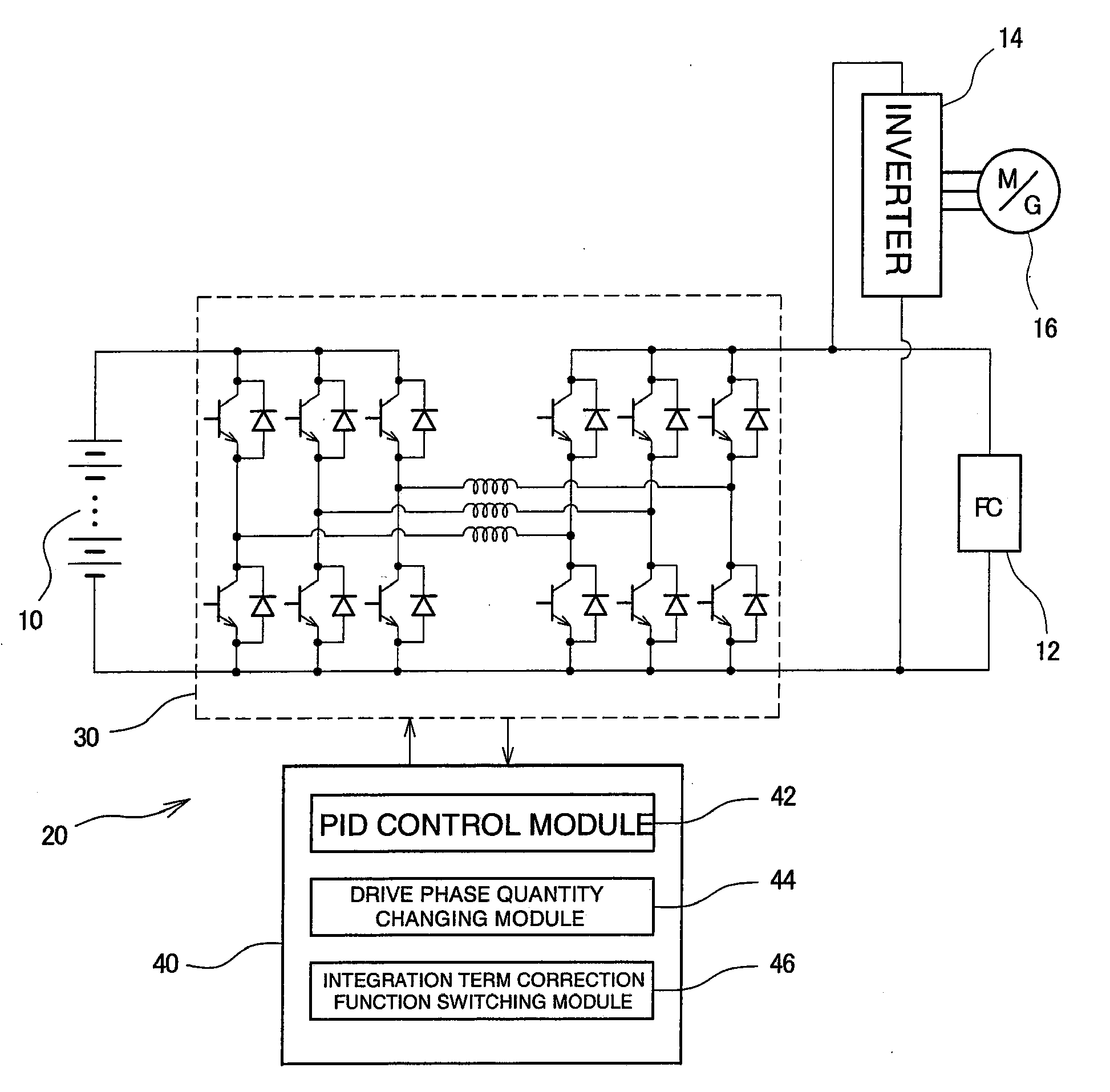
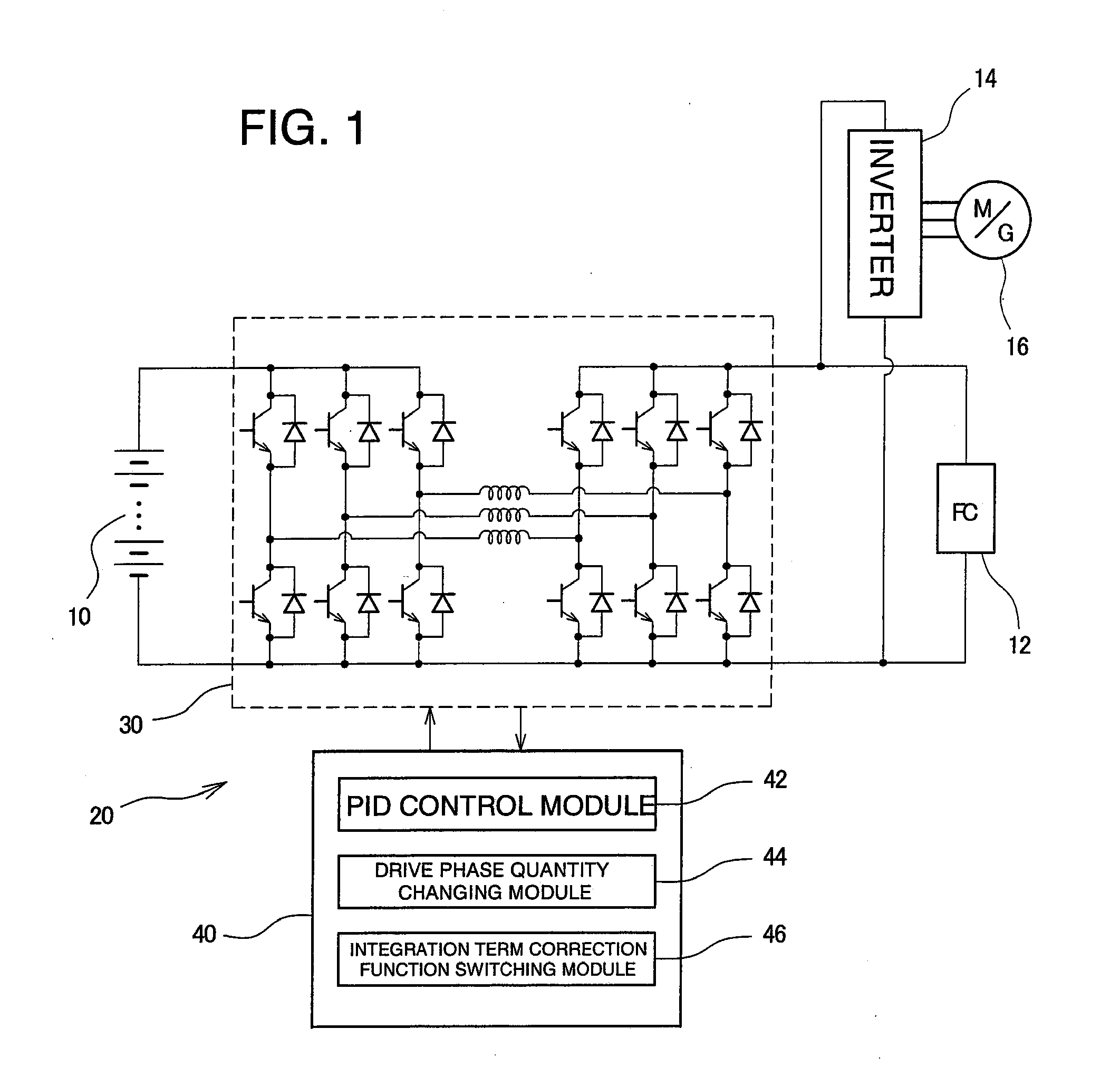
[0024]An embodiment according to the present invention will be described below with reference to the drawings. A vehicle-mounted power supply system connected to a vehicle driving motor / generator will be described as a power supply system to which a converter control device is applied. However, the present invention is applicable to any power supply system other than that for vehicle, for example, the power supply system fixed in a building. Furthermore, a system in which a nickel hydrogen secondary battery is a first power source and in which a solid polymer membrane fuel cells are a second power source will be described below as the power supply system to which the converter control device is applied. However, the present invention is applicable to any other type of power source. For example, the secondary battery may be of a lithium ion type, and the fuel cells may be of a type other than a solid electrolyte one. Furthermore, a configuration in which three converter circuits are ...


PUM


Abstract

A converter control device includes a converter device formed by three converter circuits connected together in parallel between a secondary battery as a first power source and a fuel cell as a second power source. A control unit includes: a PID control module for controlling the converter device by PID control and executing a desired voltage conversion; a drive phase quantity changing module for changing the number of drive phases of the converter device in accordance with the passing power of the converter device; and an integration term correction function switching module which switches the PID control integration term correction function when changing the number of drive phases.

Description

BACKGROUND OF THE INVENTION[0001]The present invention generally relates to a converter control device, and particularly to a converter control device including an arrangement in which a plurality of converters are connected together in parallel, the converters being connected between a first power source and a second power source, and each having a plurality of switching elements and reactors to perform a voltage conversion in both directions, the converter control device changing the number of converter phases to be driven according to converter passing power.[0002]In power supply systems using fuel cells, a voltage converter raising or dropping the voltage of an output from a secondary battery is provided and connected to an output terminal of the fuel cells to supply power. The purpose of the provision of the voltage converter is to deal with a fluctuation in load exceeding the power generation capacity of the fuel cells, to improve system efficiency, and to recover regenerative...

Claims


Application Information

Patent Timeline
IPC IPC(8): H02M3/335
CPCB60R16/03H02J1/102H02P27/06H02M3/1584H02P23/0036H02M3/1582H02P23/0004H02J2310/46H02M3/155
Inventor MANABE, KOTAHASEGAWA, TAKAHIKOMAENAKA, TAKESHI
Owner TOYOTA JIDOSHA KK
Why Eureka
Try Eureka