Fuel cell system

a fuel cell and system technology, applied in the field of fuel cell systems, can solve the problems of thermal degradation of the electrolyte membrane in the fuel cell stack, and it is not possible for the intercooler to prevent excessive temperature increase, so as to prolong the power generation operation time of the fuel cell, the effect of prolonging the tim

Active Publication Date: 2009-12-24
TOYOTA JIDOSHA KK
View PDF1 Cites 20 Cited by
  • Summary
  • Abstract
  • Description
  • Claims
  • Application Information

AI Technical Summary

Benefits of technology

[0013]With the fuel cell system of the present invention, it is possible to extend the time in which the fuel cell operates to generate power while preventing supply of reaction gas having the excessively increased temperature to the fuel cell because the controller comprises the cooling section abnormality determining unit which determines presence or absence of the abnormality state of the cooling section of the intercooler including the coolant pump and the gas supplying device operation controlling unit which controls, when it is determined that an abnormality has occurred in the cooling section of the intercooler, the operation state of the gas supplying device according to the temperature of the reaction gas detected by the temperature detecting unit. Because such a structure is employed, the power generation operation time of the fuel cell can be extended compared to the case of the fuel cell system described in JP 2002-184435 A, in which the power generation operation by the fuel cell is stopped when an abnormality occurs in the cooling section of the intercooler, irrespective of other conditions.
[0014]When a vehicle is equipped with a fuel cell system of any of the various aspects of the present invention to form a fuel cell vehicle, it is possible to prevent continuation of the state of stopping of the fuel cell vehicle when an abnormality occurs in the cooling section of the intercooler, and to easily execute a “limp home” driving mode in which the fuel cell vehicle is driven to a repair factory or a safe side road without towing or transporting the fuel cell vehicle with other vehicles such as a towing vehicle. In addition, it is also possible to extend the time in which the power generation operation in which the power can be increased can be executed and to shorten the time required for the limp home driving mode.

Problems solved by technology

More specifically, if the oxidation gas having the excessively increased temperature is introduced to the fuel cell stack, constituent elements of the fuel cell stack such as the electrolyte membrane in the fuel cell stack may be thermally degraded.
Even when the intercooler is provided in the fuel cell system as described above, if an abnormality such as failure occurs in the constituent elements of a cooling section for cooling the intercooler, such as the coolant pump, it may not be possible for the intercooler to prevent excessive temperature increase in the oxidation gas to be sent to the fuel cell stack.

Method used


Image

  • Fuel cell system
  • Fuel cell system
  • Fuel cell system

Examples


first preferred embodiment

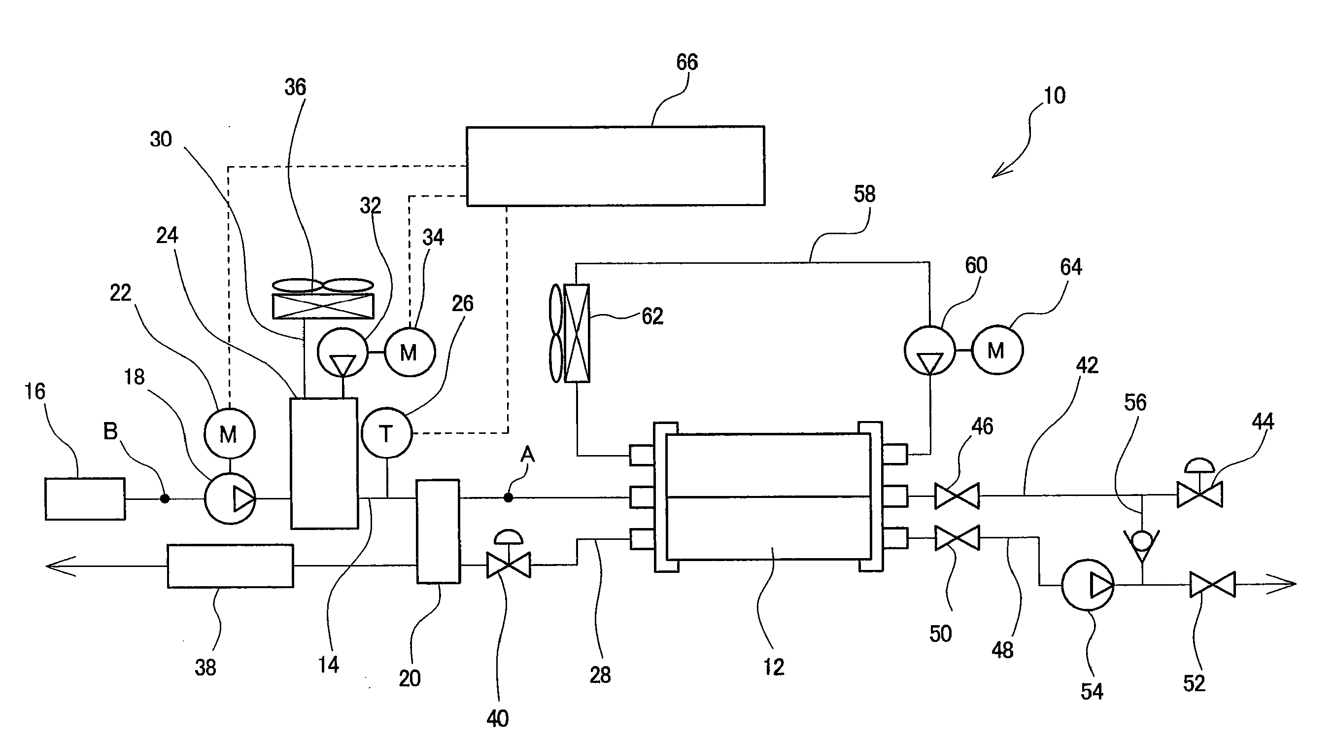
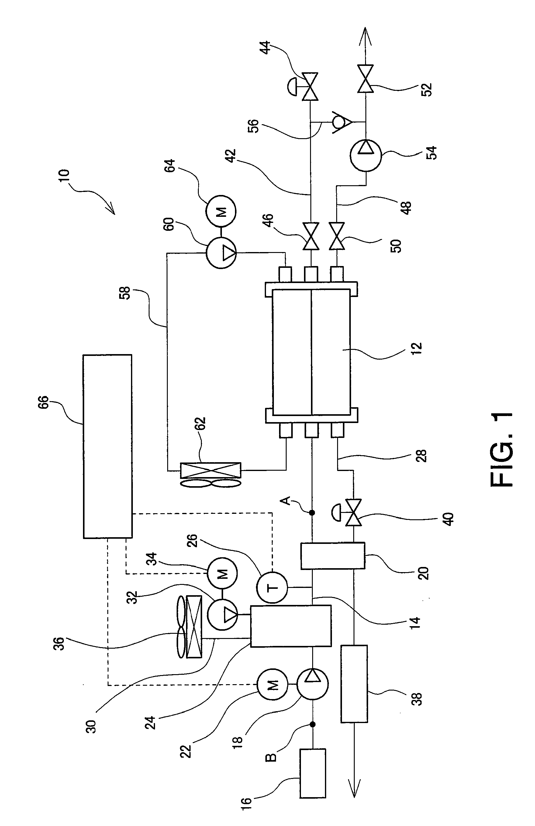
[0023]Preferred embodiments of the present invention will now be described in detail with reference to the drawings. FIGS. 1 and 2 show a first preferred embodiment of the present invention. FIG. 1 schematically shows a structure of the present embodiment.

[0024]A fuel cell system 10 is used equipped on a fuel cell vehicle, and comprises a fuel cell stack 12. In the fuel cell stack 12, a plurality of fuel battery cells are layered to form a fuel battery cell layered structure, and a collector plate and an end plate are provided on both ends of the layering direction of the fuel battery cell layered structure. The fuel battery cell layered structure, the collector plate, and the end plate are tightened by a tie-rod, a nut, etc. An insulating plate may be provided between the collector plate and the end plate.

[0025]Although the details of each fuel battery cell is not shown, each fuel battery cell may comprise, for example, a membrane-assembly formed by sandwiching an electrolyte membr...

second preferred embodiment

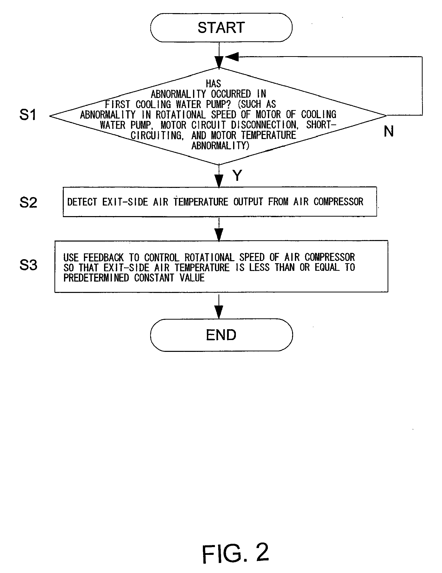
[0044]Next, FIGS. 3 and 4 show a second preferred embodiment of the present invention. In this present embodiment, the temperature sensor 26 (refer to FIG. 1) detects the exit-side air temperature which is the temperature of the air output from the air compressor 18 (refer to FIG. 1), and the controller 66 (refer to FIG. 1) determines an air compressor rotational speed limiting ratio corresponding to the detected exit-side air temperature based on data of a map as shown in FIG. 4 in the first preferred embodiment of the present invention shown with FIGS. 1 and 2. The air compressor rotational speed limiting ratio refers to a ratio of a maximum allowable rotational speed TB of the air compressor 18 corresponding to the exit-side air temperature with respect to a maximum rating rotational speed TA (=(TB / TA)*100), and is a value related to the maximum allowable rotational speed TB of the air compressor 18. For example, when the maximum rating rotational speed TA of the air compressor 1...

third preferred embodiment

[0049]Next, FIG. 5 shows a third preferred embodiment of the present invention. In this present embodiment, the temperature sensor 26 (refer to FIG. 1) does not detect the exit-side air temperature of the air output from the air compressor 18 (refer to FIG. 1), but instead detects an entrance-side air temperature which is a temperature of air before being supplied to the air compressor 18. More specifically, in the oxidation gas supply channel 14 (refer to FIG. 1), the temperature of air inside the channel at a position (position B in FIG. 1) between the air cleaner 16 (refer to FIG. 1) and the air compressor 18 is detected by the temperature sensor 26. The detection signal from the temperature sensor 26 is sent to the controller 66 (refer to FIG. 1). As the basic structure of the fuel cell system of the present embodiment is also similar to the first preferred embodiment shown in FIG. 1, the portions equivalent to those illustrated in FIG. 1 will be explained using the reference nu...


PUM

PropertyMeasurementUnit
temperatureaaaaaaaaaa

Abstract

A fuel cell system is provided with an air compressor for supplying a fuel cell stack with air; a temperature sensor for detecting the temperature of air in the gas downstream from an intercooler, at the middle of an oxidation gas supplying channel; and a control section. The control section is provided with a cooling section abnormality determining unit for determining presence or absence of an abnormality of a first cooling water pump, and an air compressor operation controlling unit for controlling the rotational speed of the air compressor in accordance with the air temperature detected by the temperature sensor when it is determined that an abnormality has occurred.

Description

TECHNICAL FIELD [0001]The present invention relates to a fuel cell system having a fuel cell stack which generates power through electrochemical reaction of reaction gases, a gas supply channel for supplying the reaction gases to the fuel cell stack, and an intercooler provided on the gas supply channel.BACKGROUND ART [0002]In a fuel cell stack, as one example, a membrane-electrode assembly (MEA) is formed with an anode-side electrode, an electrolyte membrane, and a cathode-side electrode, a fuel battery cell is formed with the membrane-electrode assembly and a separator, and a plurality of fuel battery cells are layered to form a fuel battery cell layered structure. More specifically, each fuel battery cell is formed by placing the anode-side electrode on one surface of the electrolyte membrane formed by a polymer ion exchange membrane and the cathode-side electrode on the other surface, and providing separators on both sides. A fuel cell stack which generates a high voltage is for...

Claims


Application Information

Patent Timeline
Patent Type & Authority Applications(United States)
IPC IPC(8): H01M8/04
CPCH01M8/04007H01M8/04029H01M8/04089H01M8/04097H01M8/04141H01M8/04335Y02E60/50H01M8/04686H01M8/04753H01M8/04768H01M2008/1095H01M2250/20Y02T90/32H01M8/04365Y02T90/40
Inventor BONO, TETSUYA
Owner TOYOTA JIDOSHA KK
Why Eureka
Try Eureka