System and method for mass custom manufacturing of dental crowns and crown components

a dental crown and custom manufacturing technology, applied in the field of prosthodontic systems, methods and apparatuses, can solve the problems of high labor intensity and time consumption of prosthodontic manufacturing systems, considerable amount of skilled (artisan) labor, and the prior art system described above is very time-consuming, so as to optimize the custom milling results, reduce labor, time and/or materials, and improve efficiency

Inactive Publication Date: 2009-12-24
ZIRCORE
View PDF22 Cites 45 Cited by
  • Summary
  • Abstract
  • Description
  • Claims
  • Application Information

AI Technical Summary

Benefits of technology

[0008]A principal object of the instant invention is to provide a system for simultaneously or mechanico-sequentially, designing and / or fabricating custom dental crown and bridge coping / infrastructures (Cores) and one or more other companion / collateral pieces (such as an implant abutment or crown mold) to reduce the amount of labor, time and / or materials. The process is accomplished by integrating, sharing and interpreting stored CAD / CAM digital job information, dental design and algorithms, CNC and CAM programs and advanced data warehousing and adaptive learning to achieve optimized custom milling results. Another object of the invention is to provide a system and method for mass custom production (Mass Custom Manufacturing, in anagram, MCM) of dental restorations and / or components (Cores, temporary crowns, abutments, molds to make crowns, models, etc.) thereof. Still another object of the invention is to provide a system and method for Mass Custom Manufacturing that provides increased efficiencies over the custom mass-production system of the prior art.

Problems solved by technology

Prior to the advent of the instant invention, prosthodontic manufacturing systems have been extremely labor intensive and time consuming, requiring a considerable amount of skilled (artisan) labor to custom fit prosthodontics for each case.
But in all cases, by prior art, Implant abutments must be fabricated before Crown and Bridge Cores can be designed and fabricated, and finished Crowns can only be fabricated after the completion of the Core and its geometry is known by post fabrication inspection.
The prior art system described above is very time consuming, as it requires a considerable amount of labor and time to modify the abutment and then separately manufacture the coping (Core) based upon the shape of the modified abutment, and then start on another unrelated process to build the Core to its final geometry with porcelain.
In addition, the prior art system results in substantial waste of materials as the ceramic abutment and the coping (Core) are manufactured independently and / or by different processes and / or materials.
Certainty of final geometry, size and precision is lost if shaping is accomplished in the green stage zirconium, because unpredictable shrinkage often exceeding 20% will result in subsequent required heat shrink transformation treatments.
As the conventional system for designing dental restorations described above requires that a dental restoration be designed (and built) in a derivative, linear manner from the ground up, i.e. first design the abutment, then design the coping (Core) to fit the abutment, manufacturing processes and systems have been extremely limited.
Improvements in technology have been interspersed throughout the process at various levels to replace certain functions, but the system as a whole remains relatively unchanged and inefficient.
Even though the Atlantis custom implant abutment is the product of a modern CAD / CAM design and milling process, it still has no coordinated follow-on Core process.
And it has not been archived in any manner to feed some follow-up production process.
In some instances, the CAD user will design a piece that is impossible for the CAM to mill, and all subsequent processes are thereby totally thwarted until the Core mill is resolved.
In prior art it is entirely possible that all components all the way back to the implant abutment, may have to be remade, because of the failure of designing the first component to the dimensional requirements of the actual condition in the mouth and on the master model.

Method used


Image

  • System and method for mass custom manufacturing of dental crowns and crown components
  • System and method for mass custom manufacturing of dental crowns and crown components
  • System and method for mass custom manufacturing of dental crowns and crown components

Examples


Embodiment Construction

[0029]As required, a detailed embodiment of the present invention is disclosed herein; however, it is to be understood that the disclosed embodiment is merely exemplary of the principles of the invention, which may be embodied in various forms. Therefore, specific structural and functional details disclosed herein are not to be interpreted as limiting, but merely as a basis for the claims and as a representative basis for teaching one skilled in the art to variously employ the present invention in virtually any appropriately detailed structure.

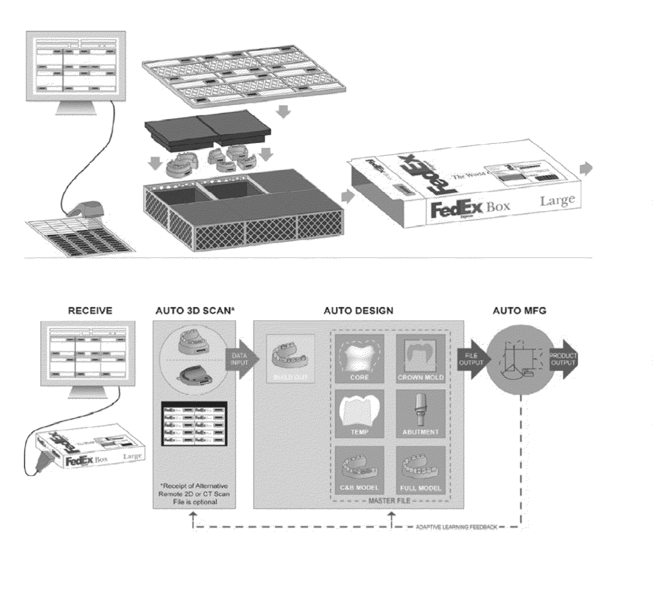
[0030]The inventive system and method of Mass Custom Manufacturing of dental crowns and crown components shall be described herein in connection with an embodiment that utilizes a deconstructive design and manufacturing method. Nevertheless it will be appreciated that alternative design and manufacturing methods may be utilized without departing from the spirit and scope of the instant invention.

[0031]Referring to FIGS. 9, 10 and 10a a Mass Cu...


PUM


Abstract

A Mass Custom Manufacturing System and methods are provided. A single master file is created for a restoration (or multiple restorations for a single patient) from a scan. Copings/cores, abutments and other companion pieces are designed using the master file through a deconstruction method allowing for simultaneous CAM of those pieces. A centralized system controls design and manufacturing, allowing the system to “learn” from feedback from the CAM operations of prior pieces and incorporate such feedback into the design phase.

Description

CROSS-REFERENCE TO RELATED APPLICATIONS[0001]This application claims priority pursuant to 35 U.S.C. 119(e) to U.S. Provisional Patent Application Ser. No. 61 / 099,566, filed Sep. 24, 2008, and is a continuation-in-part application of U.S. application Ser. No. 11 / 107,519 filed Apr. 15, 2005 and of U.S. application Ser. No. 12 / 212,256, filed Sep. 17, 2008, which is a continuation of U.S. application Ser. No. 11 / 023,950 filed Dec. 28, 2004 (now U.S. Pat. No. 7,445,449), which claims priority pursuant to 35 U.S.C. 119(e) to U.S. Provisional Patent Application Ser. No. 60 / 631,102, filed Nov. 26, 2004, U.S. Provisional Patent Application Ser. No. 60 / 566,855, filed Apr. 30, 2004 and U.S. Provisional Patent Application Ser. No. 60 / 543,038, filed Feb. 6, 2004, the entire disclosures of which are incorporated herein by reference.FIELD OF THE INVENTION[0002]The present invention relates generally to prosthodontic systems, methods and apparatuses. More particularly, the present invention is conc...

Claims


Application Information

Patent Timeline
Patent Type & Authority Applications(United States)
IPC IPC(8): G06F17/50G16Z99/00A61C5/77G06F15/18
CPCA61C5/002A61C13/0022A61C13/0004A61C5/10A61C5/20A61C5/77G16H50/50Y02P90/02G16Z99/00G06F30/00G06F2119/18G05B19/4097G05B2219/45167A61C5/73A61C8/0048A61C8/0086A61C13/09G05B2219/45145G05B2219/35134A61C8/0001
Inventor SAGER, ROBERT D.
Owner ZIRCORE
Why Eureka
Try Eureka