Generating device, generating method, program and recording medium

Inactive Publication Date: 2009-12-24
JAPAN SCI & TECH CORP +2
View PDF11 Cites 7 Cited by
  • Summary
  • Abstract
  • Description
  • Claims
  • Application Information

AI Technical Summary

Benefits of technology

[0047]According to the present invention, the “X-filling target selection problem” can be solved by selection means, and the “X-filling value selection problem” can be solved by capture transition metric calculation means and logic value assignment means. T

Problems solved by technology

A ratio by which the non-defective products can be obtained is called yield, and the yield largely affects the quality, reliability and manufacturing costs of the semiconductor logic circuit.
However, in general, the output pin (pseudo external input pin) and the input pin (pseudo external output pin) of the flip-flop of the sequential circuit cannot be directly accessed from outside.
Therefore, there are problems in the controllability of the pseudo primary input and the observability of the pseudo primary output when the combinational circuit unit is tested.
The scan test method described above, which is a very effective means, still includes the problem that more power is consumed in the test than in a normal operation.
In the case where a CMOS circuit constitutes a semiconductor logic circuit, the power consumption includes static power consumption due to leak current and dynamic power consumption due to the switching activity of logic gates and flip-flops.
Further, the latter power consumption, which is the dynamic power consumption, includes shift power consumption in a shift operation and capture power consumption in a capture operation.
Therefore, the shift power consumption is

Method used


Image

  • Generating device, generating method, program and recording medium
  • Generating device, generating method, program and recording medium
  • Generating device, generating method, program and recording medium

Examples


Example

[0058]100 generation device[0059]101 selection unit[0060]103 capture transition metric calculation unit[0061]105 logic value assignment unit

PREFERRED EMBODIMENT OF THE INVENTION

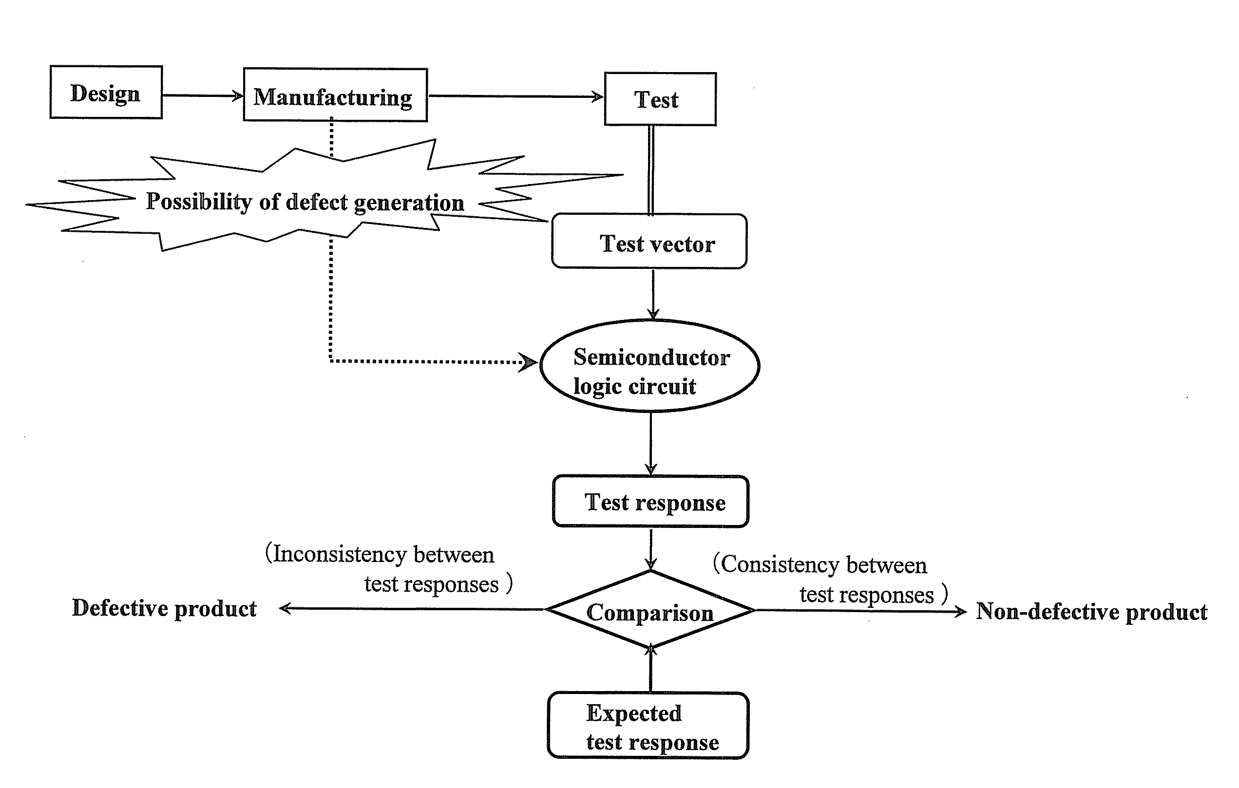
[0062]LCP X-filling described below is conducted for the X-bits in a test cube for the purpose of reducing the capture power of the resulting test vector.

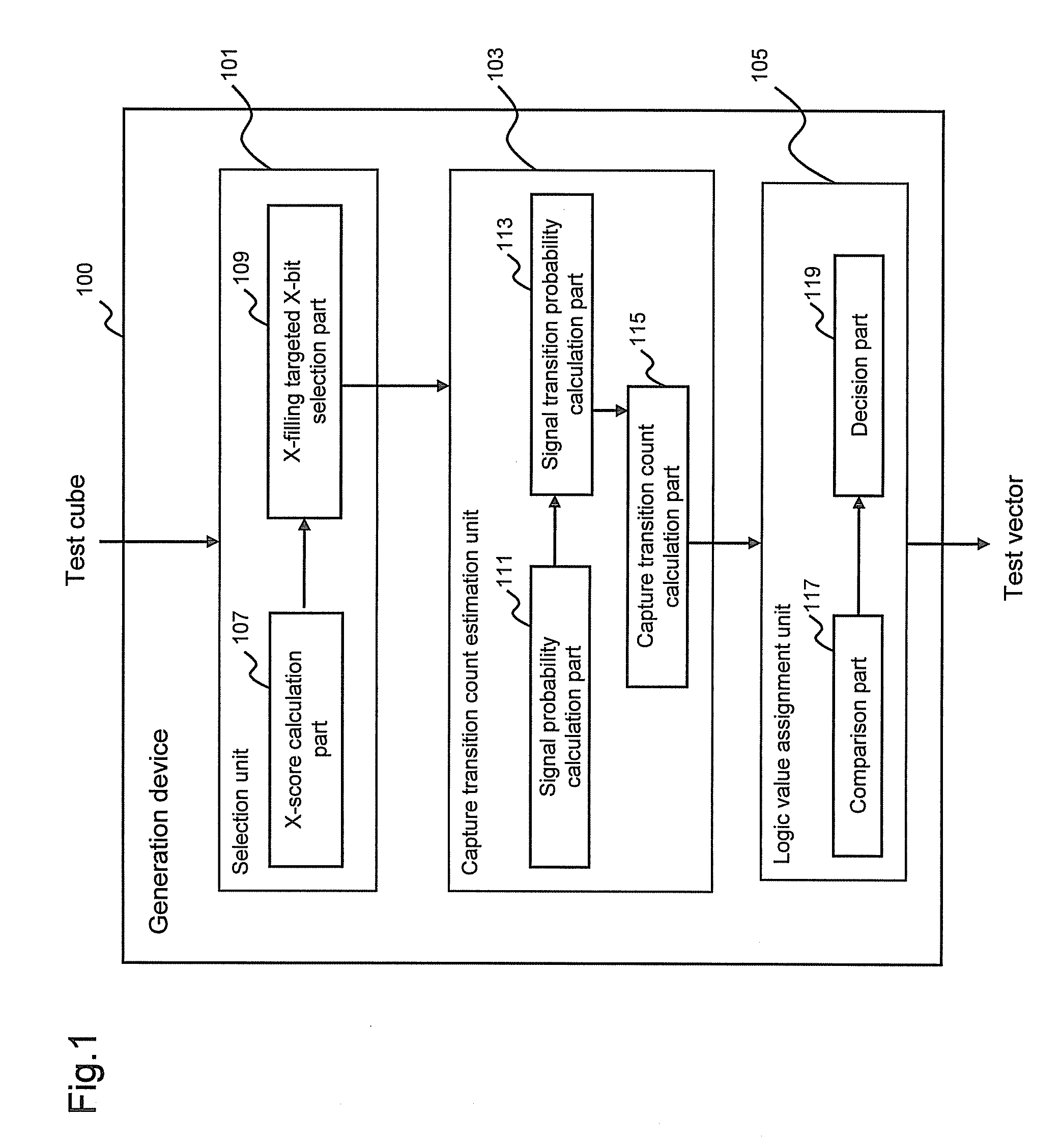
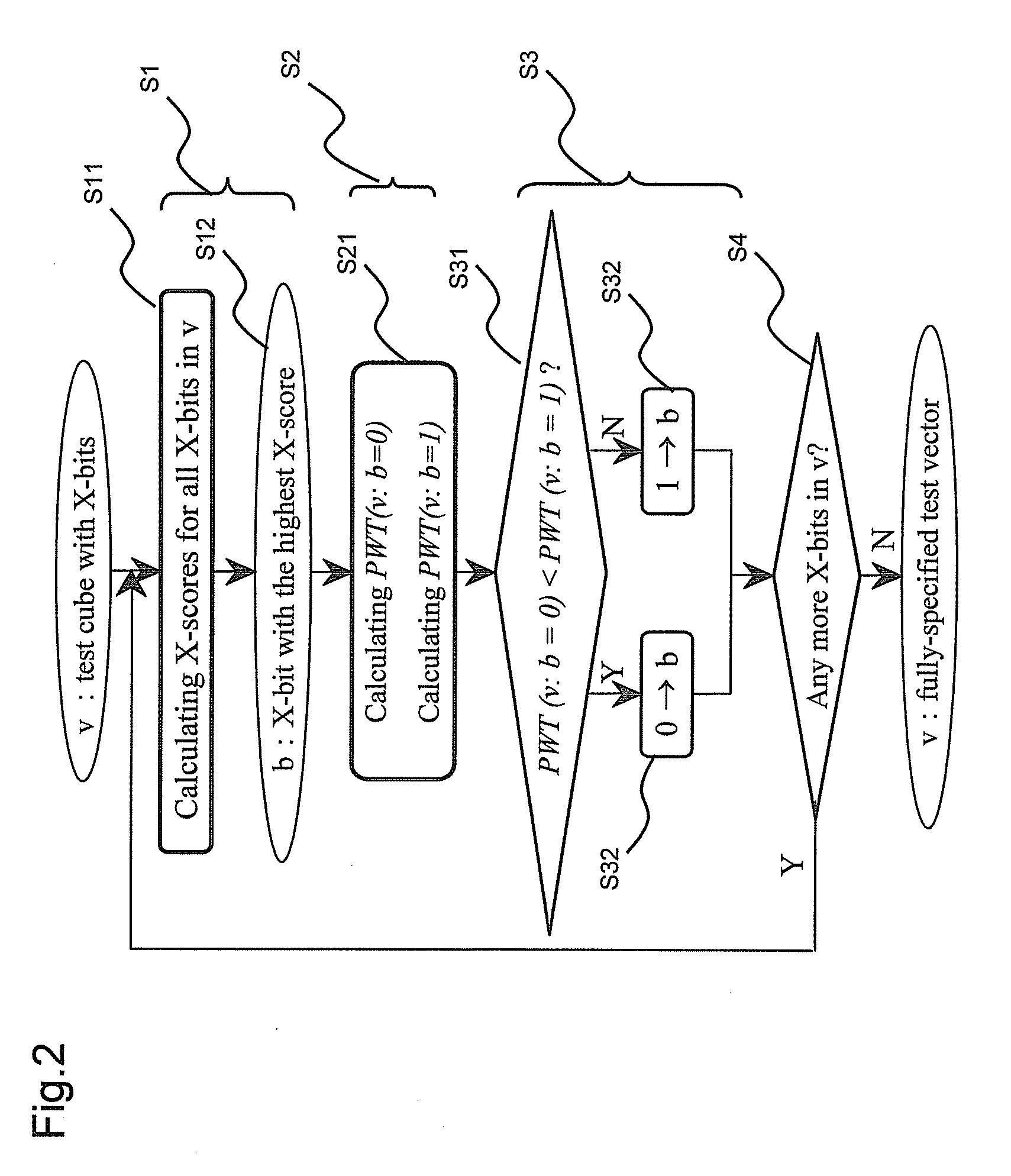
[0063]FIG. 1 is a schematic block diagram of the generation device in accordance with an embodiment of the present invention. FIG. 2 is a flow diagram which explains the behavior of the generation device in FIG. 1.

[0064]FIG. 2 shows the operation in FIG. 1 and the general overview of the new LCP X-filling method that provides sufficient guidance in X-filling, based on two concepts of the “X-score” and the “probabilistic weighted capture transition metric,” which will be described later.

[0065]The generation device 100 includes a selection unit 101, a capture transition metric calculation unit 103, and a logic value assignment unit 105. The selection unit 101 ...


PUM


Abstract

Provided are a generation device and the like for generating a test vector which can reduce capture power efficiently. The generation device 100 generates a test vector for a logic circuit by assigning logic values to each of a plurality of unspecified bits (X-bits) included in a test cube. The generation device 100 includes a selection unit 101 for selecting, among the plurality of X-bits, a target X-bit, which is a target of assigning a logic value, a capture transition metric calculation unit 103 for calculating capture transition metric caused by a test cube including an X-bit, and a logic value assignment unit 105 for assigning, to the selected target X-bit, a logic value which causes the smaller capture transition metric, by applying the capture transition metric calculation means to a first test cube obtained by assigning a logic value 0 to the selected target X-bit and to a second test cube obtained by assigning a logic value 1 to the selected target X-bit, and by comparing a capture transition metric caused by a first test cube and a capture transition metric caused by a second test cube.

Description

TECHNICAL FIELD[0001]The present invention relates to a generation device, generation method, a program capable of causing a computer to execute a generation method, and a recording medium recording this program. More specifically, the present invention relates to a generation device and the like for generating a test vector, for a logic circuit, by assigning logic values to each of a plurality of unspecified bits (X-bits) included in a test cube.BACKGROUND ART[0002]As shown in FIG. 8, a semiconductor logic circuit is shipped through three stages, which are designing, manufacture and testing stages. In the testing stage, a test vector, wherein the logic value of each logic bit is determined as either 0 or 1, is applied to the manufactured semiconductor logic circuit, and a test response from the semiconductor logic circuit is observed and compared to an expected test response, so that it is judged if the circuit is defective or non-defective. A ratio by which the non-defective produ...

Claims


Application Information

Patent Timeline
IPC IPC(8): G06F11/25G01R31/28
CPCG01R31/31721G01R31/31813G11C29/56004G11C29/10G01R31/31917
Inventor WEN, XIAOQINGKAJIHARA, SEIJIMIYASE, KOHEIMINAMOTO, YOSHIHIRODATE, HIROSHI
Owner JAPAN SCI & TECH CORP
Why Eureka
Try Eureka