Acceleration sensor with comb-shaped electrodes

a technology of acceleration sensor and comb-shaped electrode, which is applied in the direction of speed/acceleration/shock measurement, measurement devices, instruments, etc., can solve the problems of large space requirement, disadvantageously reduced rigidity of system, inability to overcome significant or intolerable offset signals, etc., to achieve low sensitivity to substrate bending, large capacitance values, and high sensitivity of acceleration sensors

Inactive Publication Date: 2009-12-31
ROBERT BOSCH GMBH
View PDF6 Cites 37 Cited by
  • Summary
  • Abstract
  • Description
  • Claims
  • Application Information

AI Technical Summary

Benefits of technology

[0009]The use according to the present invention of comb-shaped electrodes in which a parallel movement of lamellae running in parallel results in a change of a length of overlap that is evaluated as a measure of the deflection of the seismic mass results in various advantages. In this case, the zero-point error is given by dx0 / l0. Because overlap length l0 can be selected significantly larger than resting distance x0 in a distance-based capacitor system, a significant reduction occurs in offset signal dC / C relative to conventional sensor systems, given an otherwise comparable zero-point deflection dx0.
[0010]The advantages of a system in which all fastening areas are situated in a central area of the substrate can also be exploited in sensor systems according to the present invention, enabling a particularly low sensitivity to substrate bendings and similar deformations to be achieved.
[0011]In particular, if a seismic mass is realized as a frame that surrounds the electrode system, it is possible through corresponding structuring measures to accommodate all relevant connecting areas closely adjacent to one another in the center of the substrate. It will be possible to use the sensor configuration according to the present invention advantageously, in particular, in what are known as x- and y-acceleration sensors, in which a detection of accelerations takes place in the wafer plane. It is particularly advantageous if all fastening areas in which functional assemblies are fastened to the substrate are situated immediately adjacent to one another in such a way that they are situated on a line that runs transverse to the direction of deflection of the seismic mass. Changes in distance between the individual fastening areas lead in this case almost exclusively to relative movements between the functional assemblies that occur transverse to the measurement deflection of the seismic mass and thus have no influence on the overlap length. In contrast, a cross-displacement of comb-shaped electrodes that are meshed with one another has no influence on the capacitance of a capacitor formed by a pair of comb-shaped electrodes, because increases and reductions in the distance between the lamellae of the comb-shaped electrodes cancel each other out.
[0012]Through the use of comb-shaped electrodes, it is advantageously possible to realize large overlap areas in a small space, resulting in correspondingly large capacitance values and a concomitant high sensitivity of acceleration sensors designed in this way. This holds in particular if a plurality of comb-shaped electrodes connected fixedly to the substrate and a plurality of comb-shaped electrodes connected to the seismic mass respectively form pairs of comb-shaped electrodes whose overlap length is a function of the deflection of the seismic mass. In addition, for the use of differential capacitive evaluation methods it is advantageous if at least one comb-shaped electrode pair is present whose overlap length increases when there is a deflection of the seismic mass in the wafer plane, and at least one additional pair of comb-shaped electrodes is present whose overlap length decreases given the same deflection of the seismic mass in the wafer plane. The same holds correspondingly for a system of a plurality of pairs of comb-shaped electrodes.
[0013]The realization of the seismic mass as a frame surrounding the electrode system creates the possibility of using additional advantageous constructive means. The fastening of the seismic mass to the substrate can advantageously take place via a connecting beam that is fastened in a central area of the substrate and is connected at its ends to springs for the deflectable mounting of the seismic mass. These springs are advantageously realized as S-shaped flexible springs. A particularly low cross-sensitivity of the seismic mass results if the suspension is realized via a pair of S-shaped flexible springs that are fashioned mirror-symmetrically.
[0014]In accordance with the principle of a closely adjacent situation of required fastening areas, it is additionally advantageous if, on both sides of the connecting beam, bearer beams run in order to accommodate the comb-shaped electrodes that are connected fixedly to the substrate, said bearer beams also being fastened to the substrate only in a central area of the substrate. For process-technical reasons, it is advantageous if at least parts of the seismic mass and / or of the cross-webs of the comb-shaped electrodes are realized as perforated surfaces.

Problems solved by technology

However, this solution requires relatively long connecting beams between the fastening areas and the fastened structured elements, creating a large space requirement and a disadvantageously reduced rigidity of the system.
In addition, this solution relates only to an acceleration sensor in which the movement of the electrodes takes place perpendicular to one another, so that zero-point errors occur proportional to dx0 / x0.
Because, in order to achieve a sufficient sensitivity in such sensors, the rest distance x0 between the electrodes is often selected very small, relatively small zero-point deflections dx0 result in significant or intolerable offset signals that cannot be overcome under realistic operating conditions, even by the known reduction of the distances between the fastening areas on the substrate.

Method used


Image

  • Acceleration sensor with comb-shaped electrodes
  • Acceleration sensor with comb-shaped electrodes
  • Acceleration sensor with comb-shaped electrodes

Examples


Embodiment Construction

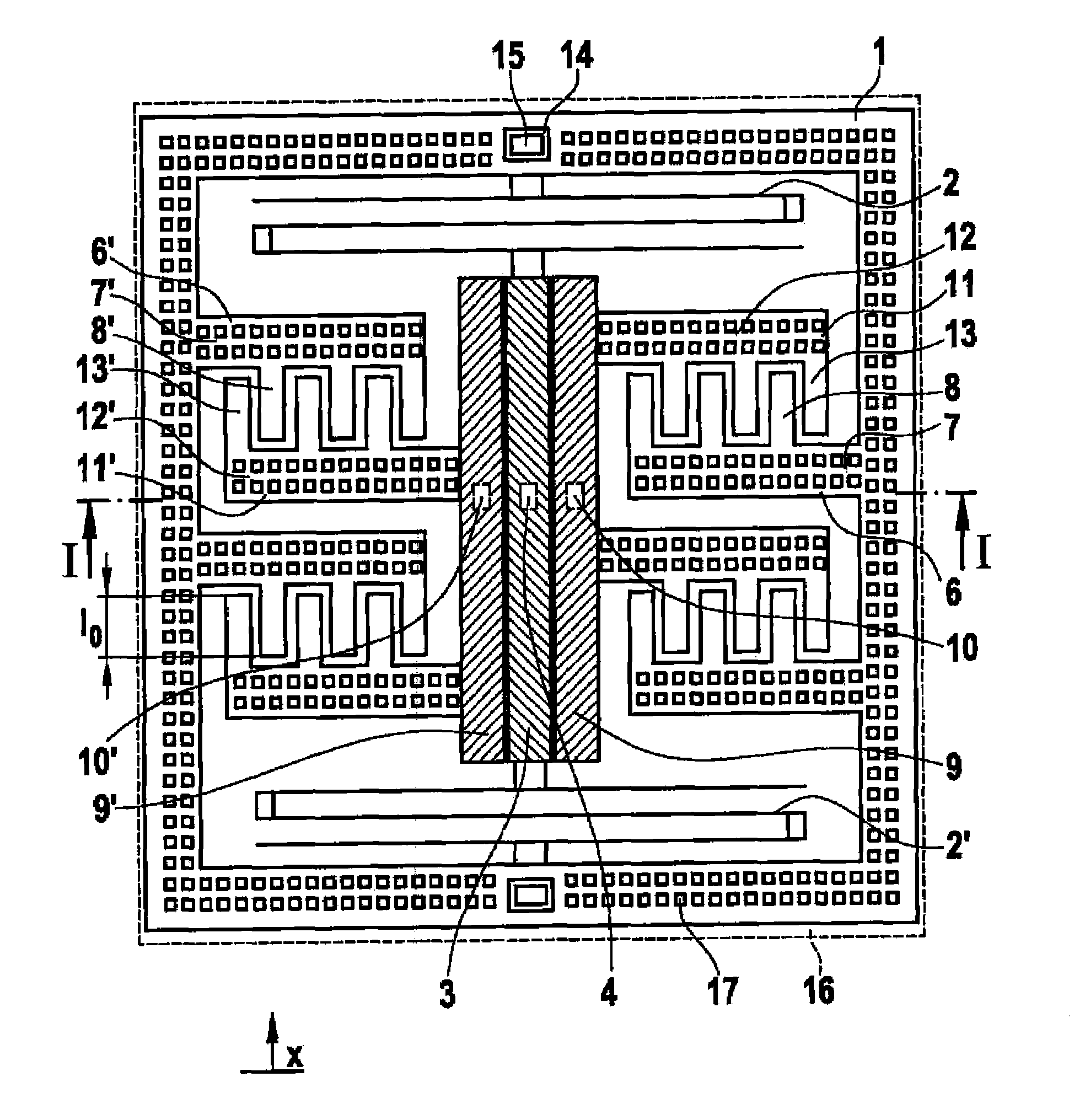
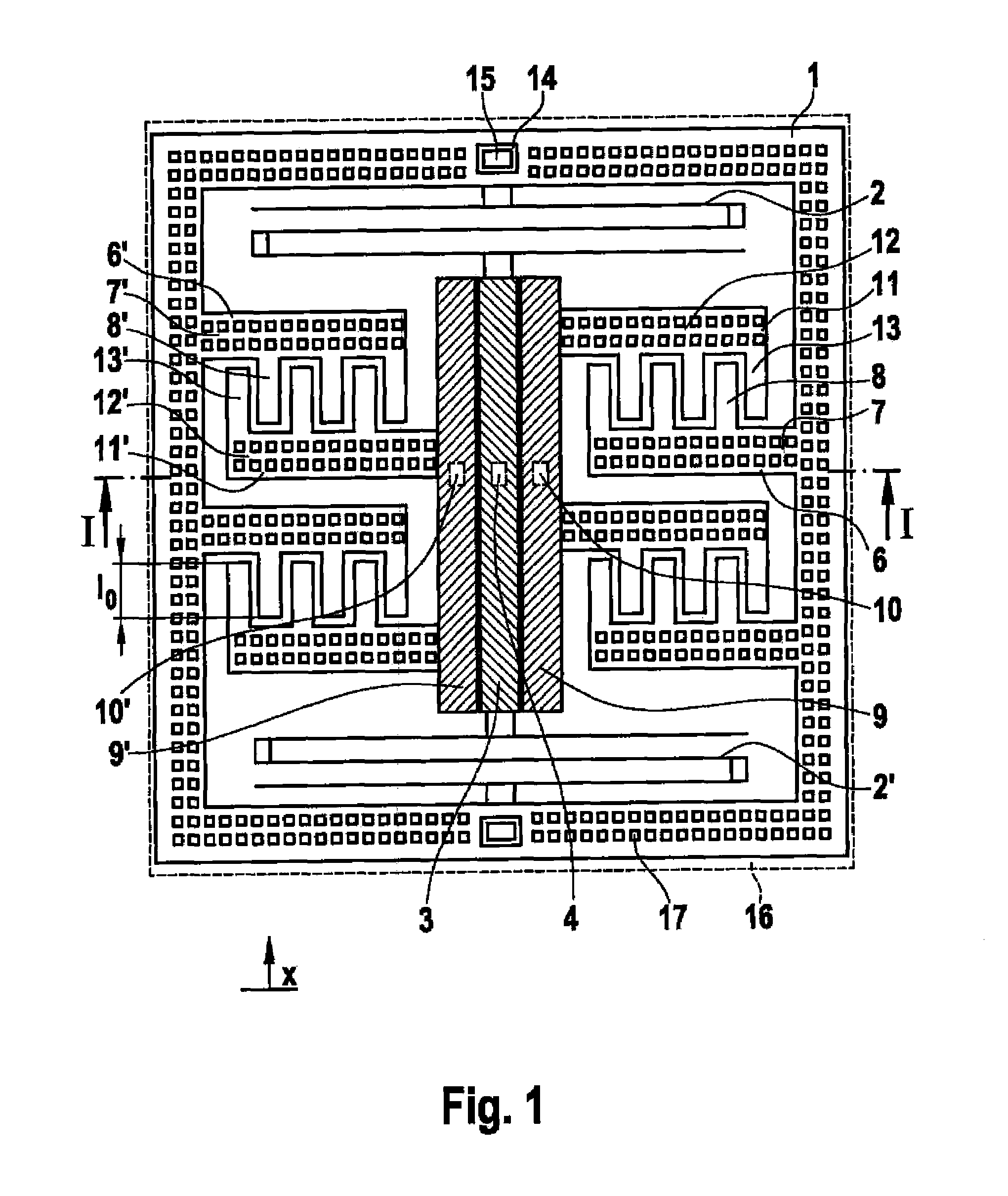
[0018]FIG. 1 shows a representation of a sensor system according to the present invention for detecting accelerations in the low-g range in a direction parallel to the wafer plane, in a top view of the plane of the seismic mass. Seismic mass 1 is fashioned as a rectangular frame that is connected, via a pair of S-shaped flexible springs 2, 2′, to a connecting beam 3, which in turn has a central fastening area 4 in which the connecting beam is structurally connected to a substrate 5. S-shaped flexible springs 2, 2′ are situated in mirror-symmetrical fashion, thus defining the direction of deflection of seismic mass 1 in the x direction, because S-shaped flexible springs 2, 2′ mutually prevent deformations of each other in the case of transverse accelerations. In this way, a low cross-sensitivity results without having to increase the spring rigidity in the x direction. This is a precondition of the suitability of the sensor according to the present invention for use in measuring smal...


PUM


Abstract

A micromechanical capacitive acceleration sensor having at least one seismic mass that is connected to a substrate so as to be capable of deflection, at least one electrode connected fixedly to the substrate, and at least one electrode connected to the seismic mass, the at least one electrode connected fixedly to the substrate and the at least one electrode connected to the seismic mass being realized as comb-shaped electrodes having lamellae that run parallel to the direction of deflection of the seismic mass, the lamellae of the two comb-shaped electrodes overlapping partially in the resting state.

Description

FIELD OF THE INVENTION[0001]The present invention relates to a capacitive micromechanical acceleration sensor having comb-shaped electrodes, distinguished by particularly low zero-point errors.BACKGROUND INFORMATION[0002]In the manufacture of micromechanical acceleration sensors, movable structures are created on a substrate by a succession of deposition and structuring steps, said structures representing mechanical spring-mass systems in which, when accelerations occur, at least one seismic mass is deflected relative to the substrate, against a known reset force. The principle of capacitive sensors is based on the fact that both electrodes connected to the seismic mass and also electrodes connected to the substrate are present that are wired together to form capacitors and that, when there is a deflection of the seismic mass, execute a movement relative to each other that corresponds to the deflection of the seismic mass, the capacitance of the capacitors formed by the electrodes c...

Claims


Application Information

Patent Timeline
Patent Type & Authority Applications(United States)
IPC IPC(8): G01P15/125
CPCG01P15/125G01P2015/0814
Inventor CLASSEN, JOHANNESHEITZ, MARKUSBENNINI, FOUND
Owner ROBERT BOSCH GMBH
Why Eureka
Try Eureka