[0027]A major
advantage of the invention is that it can be told whether the flaw is voluminous or planar. If it is for example a voluminous flaw, all the four echo displays will have an approximately comparable amplitude. In case of a planar flaw, by contrast, two amplitudes will have much higher values than the two other amplitudes.
[0028]In addition to the amplitude evaluation, the evaluation of the
travel time values can be used to obtain the size by comparing the sum of the travel times belonging to
through transmission in V-shape to the overall
travel time for undisturbed
through transmission in V-shape configuration. The difference between these two values yields the extension of the reflector in the corresponding insonification direction. Accordingly, the extension results from the difference between the
travel time for a complete
through transmission in V-shape and the sum of the travel times. In accordance with the invention, the method described is repeated for all the flaws and discontinuities in the cross section under test. According to need, testing can be repeated accordingly with other insonification angles in order to even further improve detection of the actual flaw size. In order to ensure perfect measurement, through transmission in V-shape should be performed at time intervals between the two array probes for controlling
coupling. The method described can be repeated with corresponding frequency in a next dimension, meaning for example along the course of a
weld seam, in order to be capable of testing a
weld seam or also one single flaw along its entire length. In accordance with the invention, it is also possible to move the array probes so to say virtually alongside the
weld seam or the flaw. The insonification point can be displaced both across the weld seam and alongside the weld seam. If the array probes have the corresponding size, very large surfaces or lengths can be tested without mechanically displacing the array probes. In accordance with the invention, the two array probes are mechanically joined together. It has been found particularly advantageous if the distance between them can be changed or if the mechanical connection can be adjusted in length. The mechanical connection can comprise a scale from which the distance between the two array probes can be read. Advantageously, the mechanical connection consists of a kind of frame that comprises two reception regions for a respective array probe. These two reception regions are joined together through a mechanical connection and can be moved toward each other or away from each other. In a particularly advantageous implementation variant, the distance between the two reception regions is constantly calculated electronically and is transmitted to the
electronic unit for further
processing and computing. Thus, a double control is obtained, namely through the sound duration from one array probe to the other and through the electronic distance control. The sound path is referred to as the V-path. In accordance with the invention, the frame-like mechanical connection is configured to be flexible so that light irregularities on the
coupling surface of the probe can be leveled out.
[0029]Insonification from two directions also effects that a flaw which lies at an incline can be determined quickly in two directions with respect to its propagation. The data of the two array probes are received by an
electronic unit and are immediately processed. Thus, two images of the flaw are generated at the same time and are immediately placed one above the other and can be grown directly by the operator. Accordingly, the method of the invention is very effective and fast.
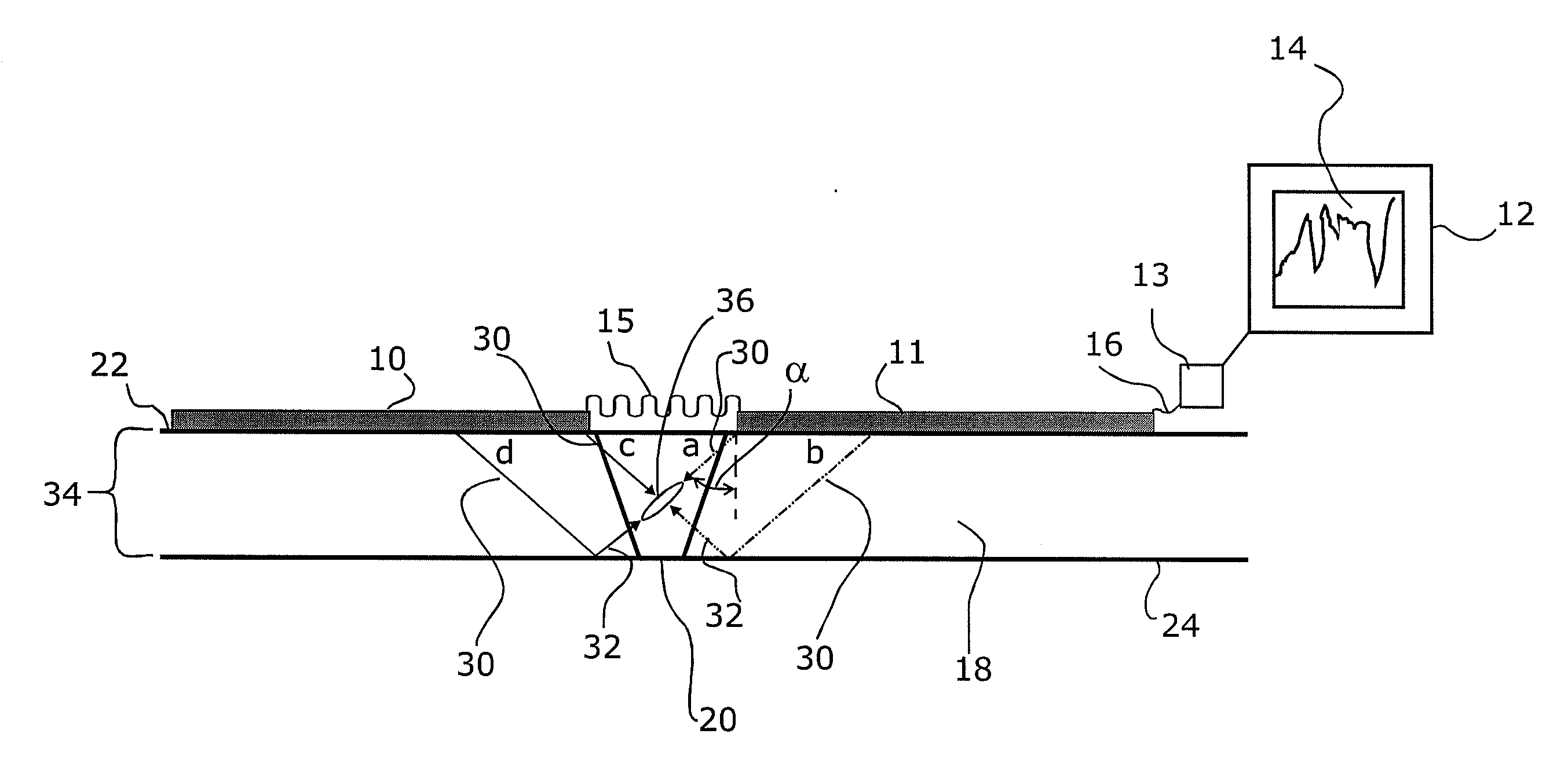
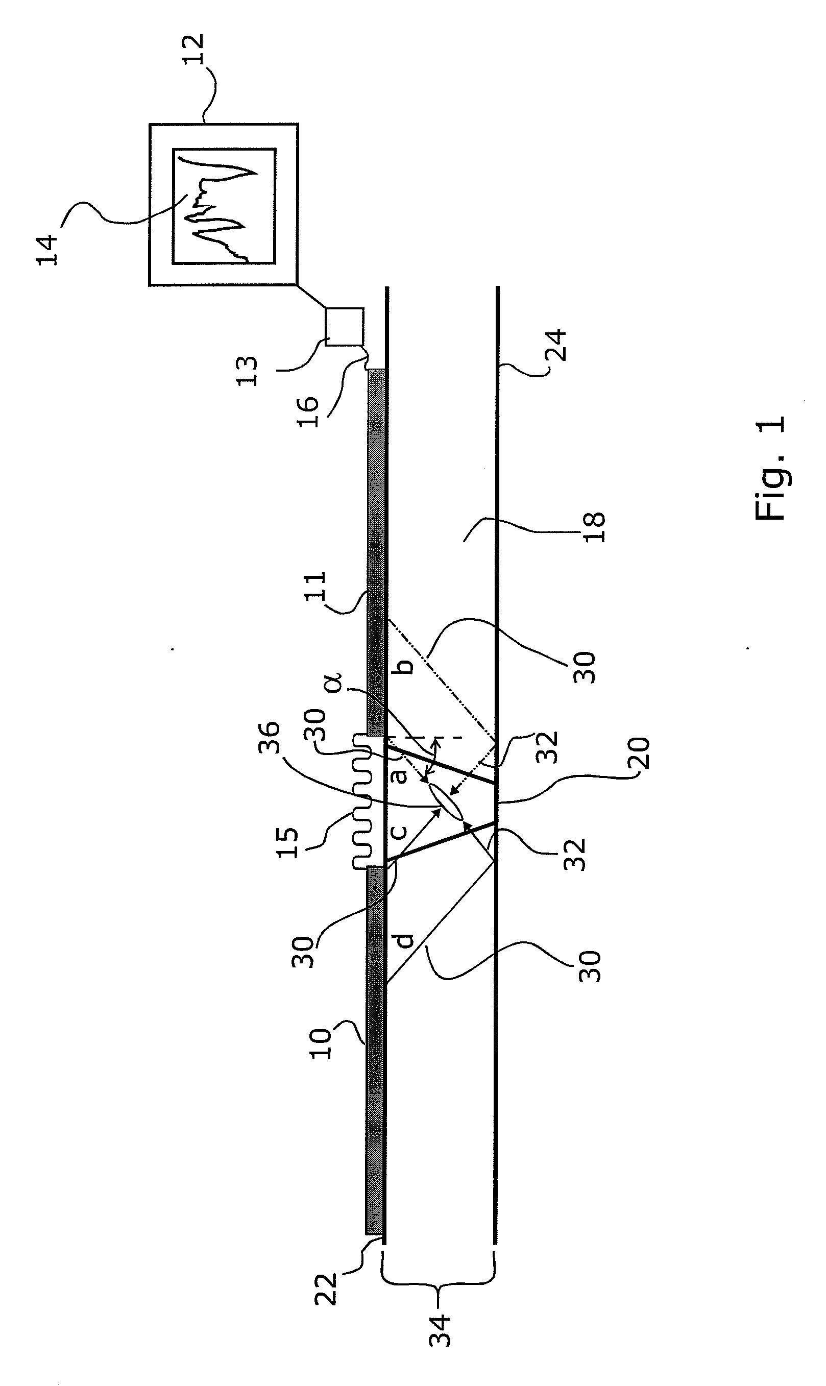
[0030]The measurement result is thereby not imaged or not only imaged as what is referred to as an A-scan but the geometry of the body under test is shown on the display. The geometry of the body under test is particularly apparent when the body under test is shown in cross section. This is possible if the wall thickness of the body under test is known. Since the insonification angle at which the sound is insonified into the body under test is known, it is also possible to image the path the sound travels through the body under test. The image yields particular information if the dimensions of relevant regions to be inspected can be included in the cross-sectional image. This is particularly helpful and easy when inspecting weld seams. Accordingly, one obtains an image in which two
steel plates, which are joined together at their end through a weld seam, are shown in cross section. Accordingly, the weld seam is shown through lines between the two
steel plates. With the help of the DGS or reference standard method and / or by calculating the extension of the flaw from the computed sound path differences, a detected flaw is directly shown true to scale in this cross-sectional image.
[0031]Accordingly, it is apparent which path the sound takes from the array probes through the body under test and in which legs or at which sites the sound hits the flaw. The prerequisite of such a
system is, as already explained, that the insonification angles and the wall thickness of the body under test are known. From this information, the sound path for each leg and, as a result thereof, the transition from one leg to the next or the point at which the reflection of the sound from the coupling surface or from the back wall occurs is easy to compute.
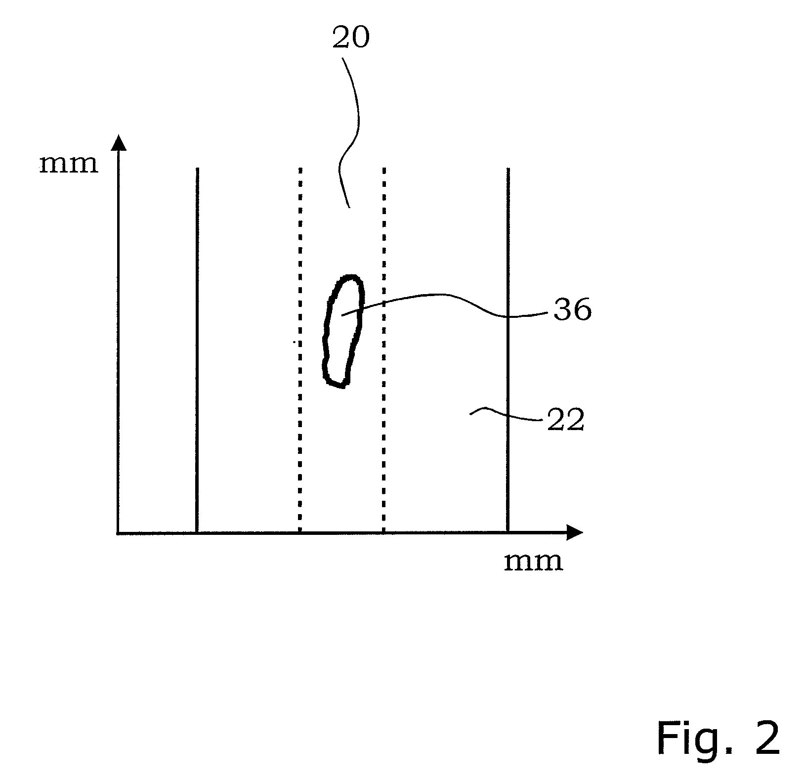
[0032]On the basis of this image, it is possible to give the operator
relevant information about the flaw, in particular with respect to its size and orientation, if the operator proceeds according to the method described herein after.

