Manufacturing method of printed circuit board

a manufacturing method and printed circuit board technology, applied in the direction of printed circuit, cable/conductor manufacturing, printed element electric connection formation, etc., can solve the problem of difficult to form a pattern having the thickness desired by a user, the thickness of the plated material is not uniform, and the pattern may have a possibility of more excessive thickness deviation, etc. problem, to achieve the effect of high density printed circuit board

Inactive Publication Date: 2009-12-31
SAMSUNG ELECTRO MECHANICS CO LTD
View PDF2 Cites 9 Cited by
  • Summary
  • Abstract
  • Description
  • Claims
  • Application Information

AI Technical Summary

Benefits of technology

[0014]The present invention provides a manufacturing method of a high density printed circuit board having reliability.

Problems solved by technology

However, according to the related art, when a plating is performed in order to form the via 6, and the patterns 7 and 8, the thickness of the plated material is not uniform.
Besides, since there is a case where an excessive etching is processed lest the seed layer 4 should remain when removing the seed layer 4, the pattern may have a possibility of occurrence of more excessive thickness deviation.
Due to the reason, it is difficult to form a pattern having a thickness desired by a user.

Method used


Image

  • Manufacturing method of printed circuit board
  • Manufacturing method of printed circuit board
  • Manufacturing method of printed circuit board

Examples


Embodiment Construction

[0029]Since there can be a variety of permutations and embodiments of the present invention, certain embodiments will be illustrated and described with reference to the accompanying drawings.

[0030]Terms such as “first” and “second” can be used in describing various elements, but the above elements shall not be restricted to the above terms. The above terms are used only to distinguish one element from the other.

[0031]The terms used in the description are intended to describe certain embodiments only, and shall by no means restrict the present invention. Unless clearly used otherwise, expressions in the singular number include a plural meaning. In the present description, an expression such as “comprising” or “consisting of” is intended to designate a characteristic, a number, a step, an operation, an element, a part or combinations thereof, and shall not be construed to preclude any presence or possibility of one or more other characteristics, numbers, steps, operations, elements, p...


PUM


Abstract

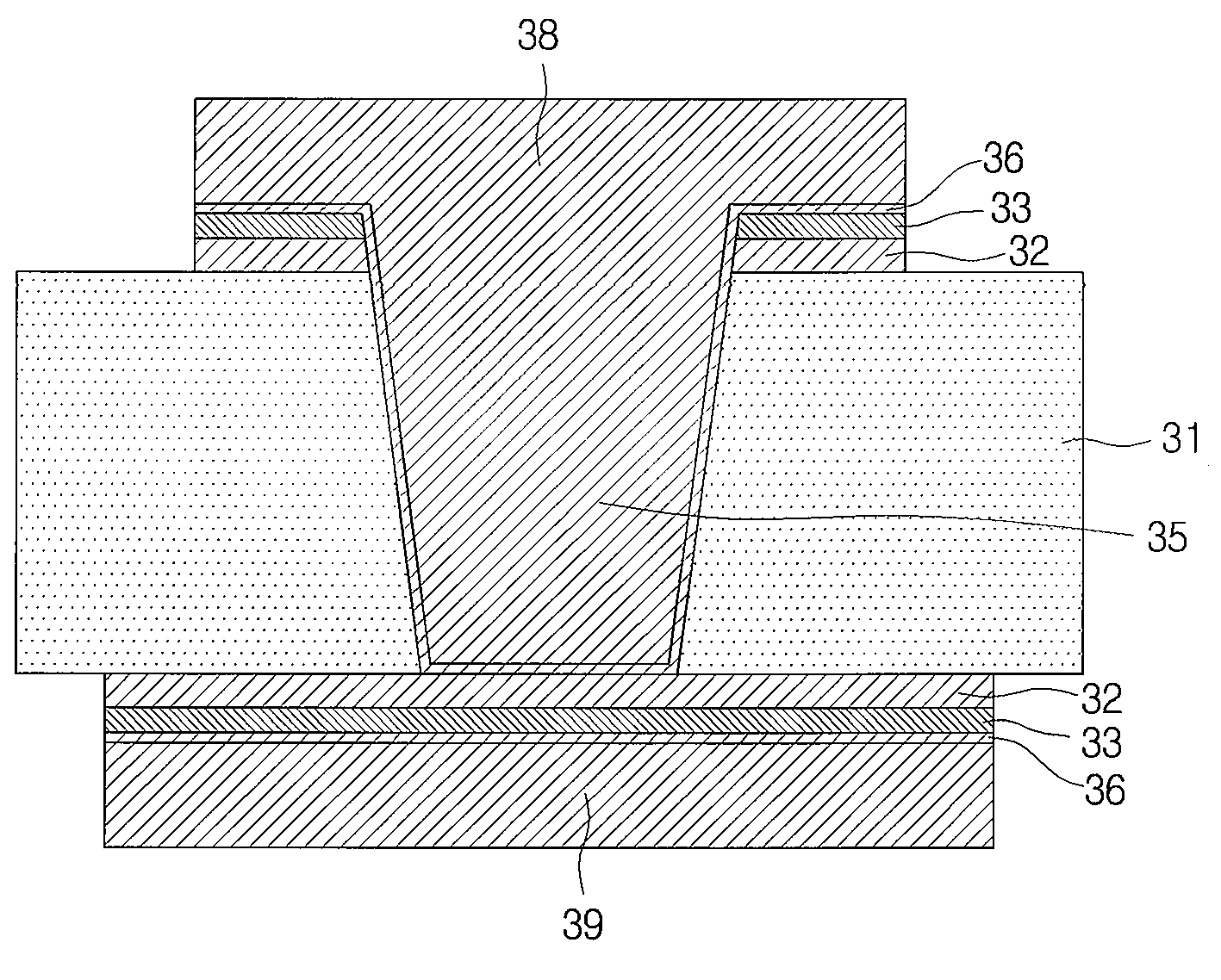
Disclosed is a manufacturing method of a printed circuit board. The method in accordance with an embodiment of the present invention includes: providing a laminated substrate having an insulator as well as a first metal layer and a second metal layer, which are sequentially laminated on one side of the insulator; processing a via hole in the laminated substrate; forming a seed layer on an inner wall of the via hole and on a surface of the second metal layer; plating an inside of the via hole and the surface of the second metal layer with a conductive material that is different from a material of the second metal layer; etching the seed layer and the conductive material, formed on the second metal layer; etching the second metal layer; and forming a first circuit pattern by selectively etching the first metal layer.

Description

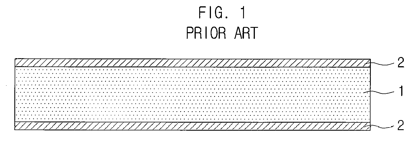
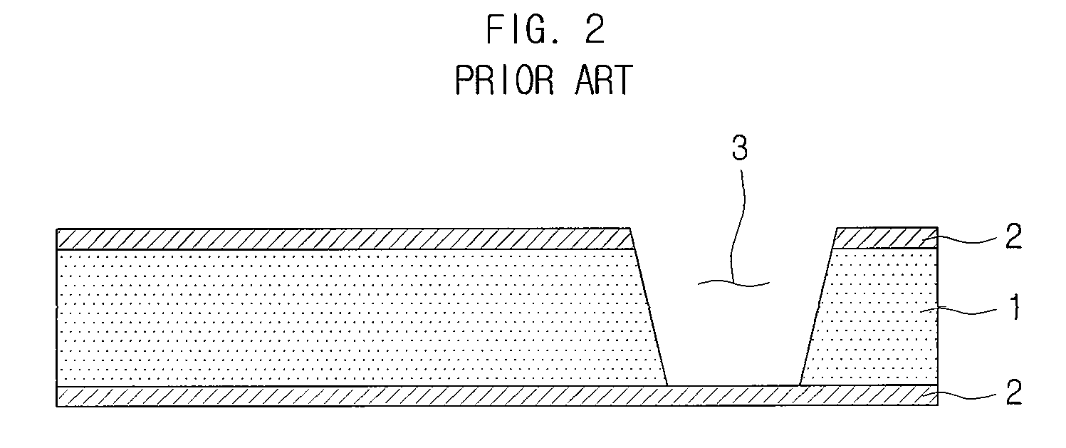
CROSS-REFERENCE TO RELATED APPLICATIONS[0001]This application claims the benefit of Korean Patent Application No. 10-2008-0062649, filed with the Korean Intellectual Property Office on Jun. 30, 2008, the disclosure of which is incorporated herein by reference in its entirety.BACKGROUND[0002]1. Technical Field[0003]The present invention relates to a manufacturing method of a printed circuit board.[0004]2. Description of the Related Art[0005]At present, in manufacturing a rigid substrate, a copper clad laminate (CCL) is commonly used as a core material. With a method of laminating layers on the copper clad laminate, a multi-layer substrate is manufactured. Here, the copper clad laminate signifies a material made of an insulator 1 added by a glass fiber, etc., having copper foils 2 formed on both sides thereof, as shown in FIG. 1.[0006]Recently, with increasing demands for portable, light and thin electronic devices having many abilities, a thin printed circuit board having high densit...

Claims


Application Information

Patent Timeline
Patent Type & Authority Applications(United States)
IPC IPC(8): B44C1/22
CPCH05K3/0035H05K3/108H05K3/421H05K3/427H05K3/4652H05K2203/1388H05K2201/0394H05K2201/09563H05K2203/0361H05K2203/0384H05K2201/0341H05K3/42H05K3/06
Inventor KANG, MYUNG-SAM
Owner SAMSUNG ELECTRO MECHANICS CO LTD
Why Eureka
Try Eureka