Flexural disc fiber optic sensor

a fiber optic sensor and flexural disc technology, applied in the field of fiber optic sensors, can solve the problems of increased cross-axis sensitivity, poor sensitivity of strain measurements, unwanted effects, etc., and achieve the effects of minimizing the response to non-axial forces, reducing unwanted cross-axis sensitivity of devices, and large response to axial forces

Inactive Publication Date: 2009-12-31
SCHLUMBERGER TECH CORP
View PDF3 Cites 4 Cited by
  • Summary
  • Abstract
  • Description
  • Claims
  • Application Information

AI Technical Summary

Benefits of technology

[0012]It will be appreciated that the flexibility of the axially-aligned, outer-edge-connected flexural discs together with the outer-edge-connected proof mass provide for a relatively large response to axial forces, while the radia

Problems solved by technology

As a result, the sensitivity of the strain measurements is poor although the response extends to high frequency.
However, such additional mass can also cause unwanted effects, including increased cross-axis sensitivity (i.e., deformation of the flexural disc under any non-axial acceleration).
Such cross-axis sensitivity can lead to measurement inaccuracies and thus render such prior art fiber optic sensor design

Method used


Image

  • Flexural disc fiber optic sensor
  • Flexural disc fiber optic sensor
  • Flexural disc fiber optic sensor

Examples


Embodiment Construction

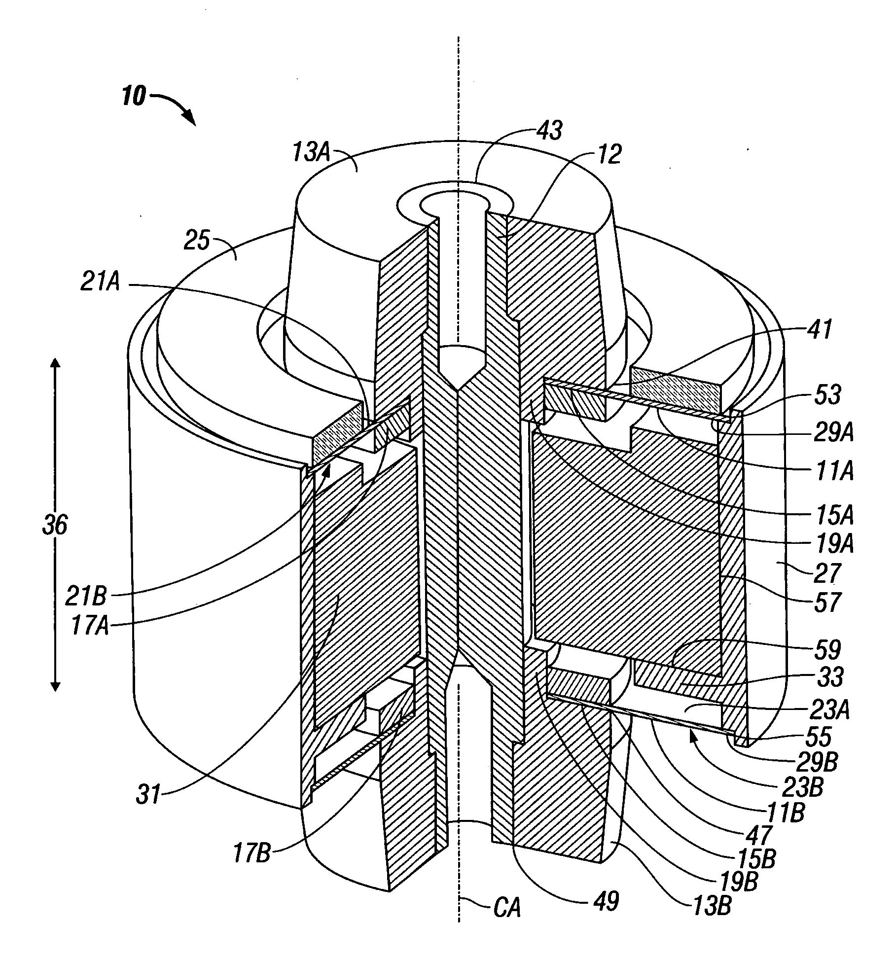
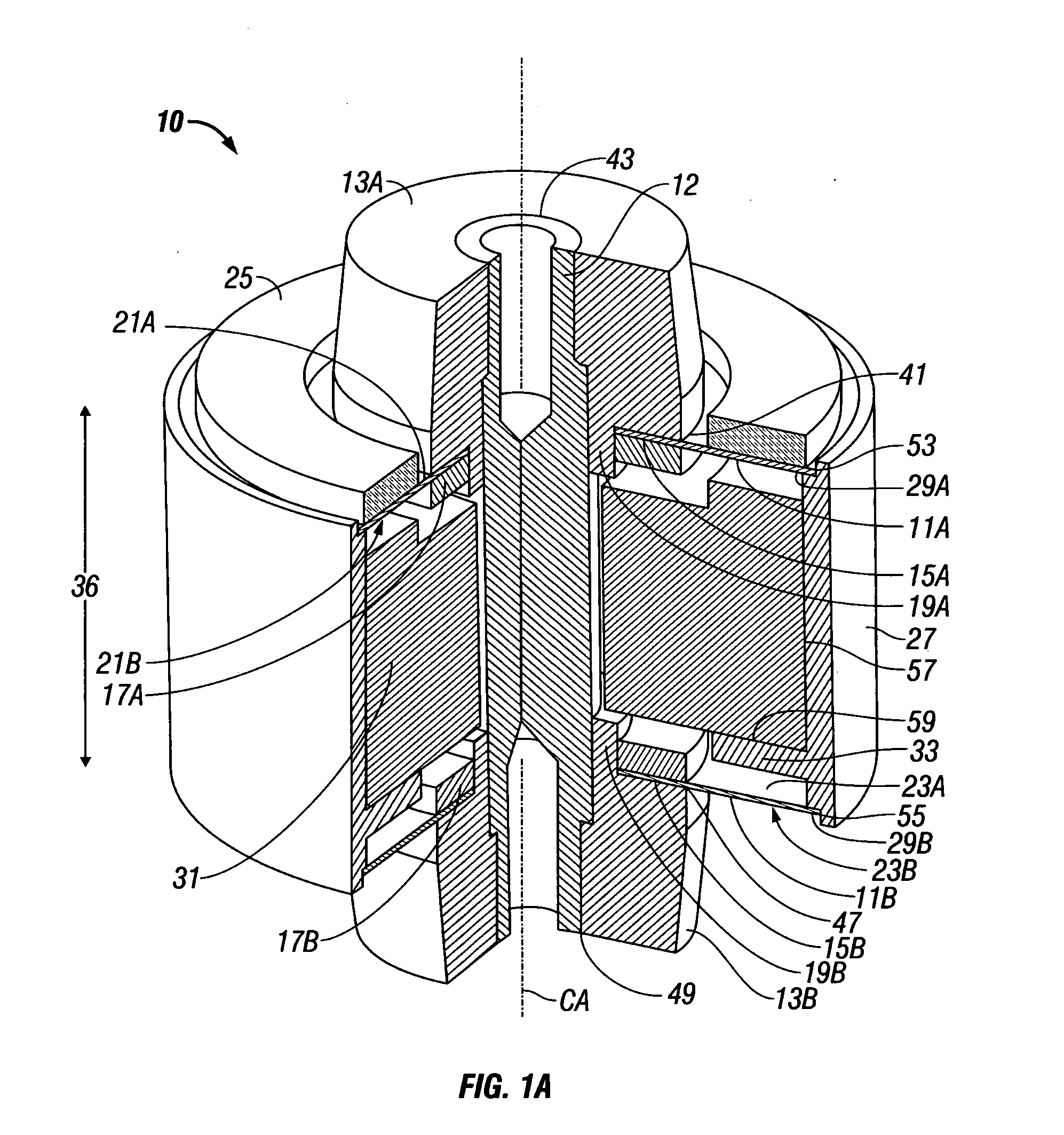
[0017]Turning now to FIG. 1A, a fiber optic sensor 10 according to the present invention includes a top flexural disc 11A and a bottom flexural disc 11B that are rigidly attached to a central support structure (e.g., the center post 12 and corresponding central support members 13A, 13B). In a first embodiment, the radially inner portion 15A of the top flexural disc 11A is permanently affixed between the central support member 13A and a backing disc 17A by welding, adhesive material, or other suitable means (for example, by welding along the interface 41 through the radially inner portion 15A of the top flexural disc 11A to the central support member 13A). The backing disc 17A interfaces to an annular flange portion 19A of the central support member 13A. The central support member 13A is rigidly attached to the center post 12 by welding, adhesive material, or other suitable means (for example, by welding along an interface 43 therebetween adjacent the top wall of the central support ...


PUM


Abstract

A fiber optic sensor employs a central support structure and at least two flexural discs spaced apart from one another along a central axis. Radially-inner portions of the flexural discs are rigidly attached to the central support structure. A fiber optic coil is affixed to one of the flexural discs. At least one proof mass is disposed between the flexural discs. Coupling means rigidly connects together radially outer edge portions of the flexural discs and rigidly connects the at least one proof mass to such outer edge portions. The flexibility of the axially-aligned outer-edge-connected flexural disc arrangement, together with the outer-edge-connected proof mass, provide for a relatively large response to axial forces. The radial stiffness of the axially-aligned outer-edge-connected flexural disc arrangement minimizes the response to non-axial forces. By limiting the response to non-axial forces, unwanted cross-axis sensitivity of the device is reduced and unwanted resonances are eliminated. The seismic mass may comprise a tungsten body.

Description

BACKGROUND OF THE INVENTION[0001]1. Field of the Invention[0002]This invention relates broadly to fiber optic sensors for measuring linear acceleration. More particularly, this invention relates to fiber optic sensors that employ an optical fiber coil affixed to a flexural disc.[0003]2. Description of Related Art[0004]The flexure or strain of an optical fiber coil affixed to a flexible disc is a well-known basis for measuring acceleration resulting from momentum forces acting on the disc in a direction normal to the disc. The amount of flexure is determined interferometrically, where interferometric measurements of strain in the optical fiber coil provide high resolution, high data rates, require low power, are immune to electromagnetic interference, and can readily be adapted for remote sensing and / or rugged applications.[0005]The mass which provides the inertia and hence the force to cause flexure of the disc usually consists of the disc itself and the optical fiber coil affixed t...

Claims


Application Information

Patent Timeline
IPC IPC(8): G01P15/093
CPCG01P15/093
Inventor BRADY, DOMINIC
Owner SCHLUMBERGER TECH CORP
Why Eureka
Try Eureka