

Compressible fluid pressure actuator driving mechanism and control apparatus thereof
- Summary
- Abstract
- Description
- Claims
- Application Information
AI Technical Summary
Benefits of technology
Problems solved by technology
Method used
Image

Examples
first embodiment
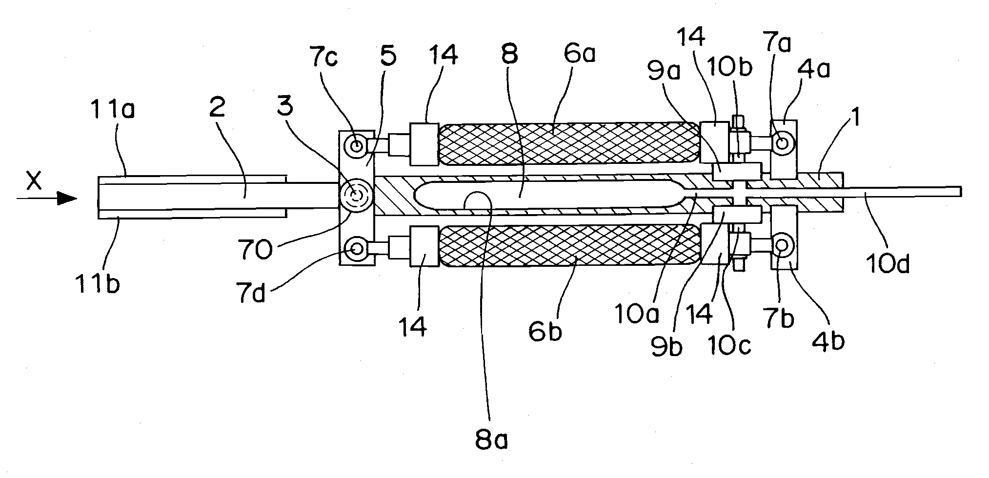
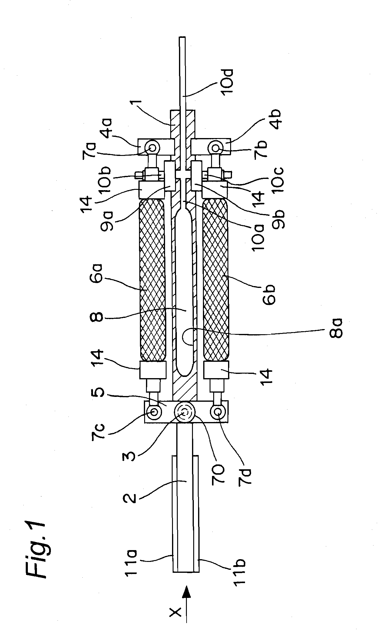
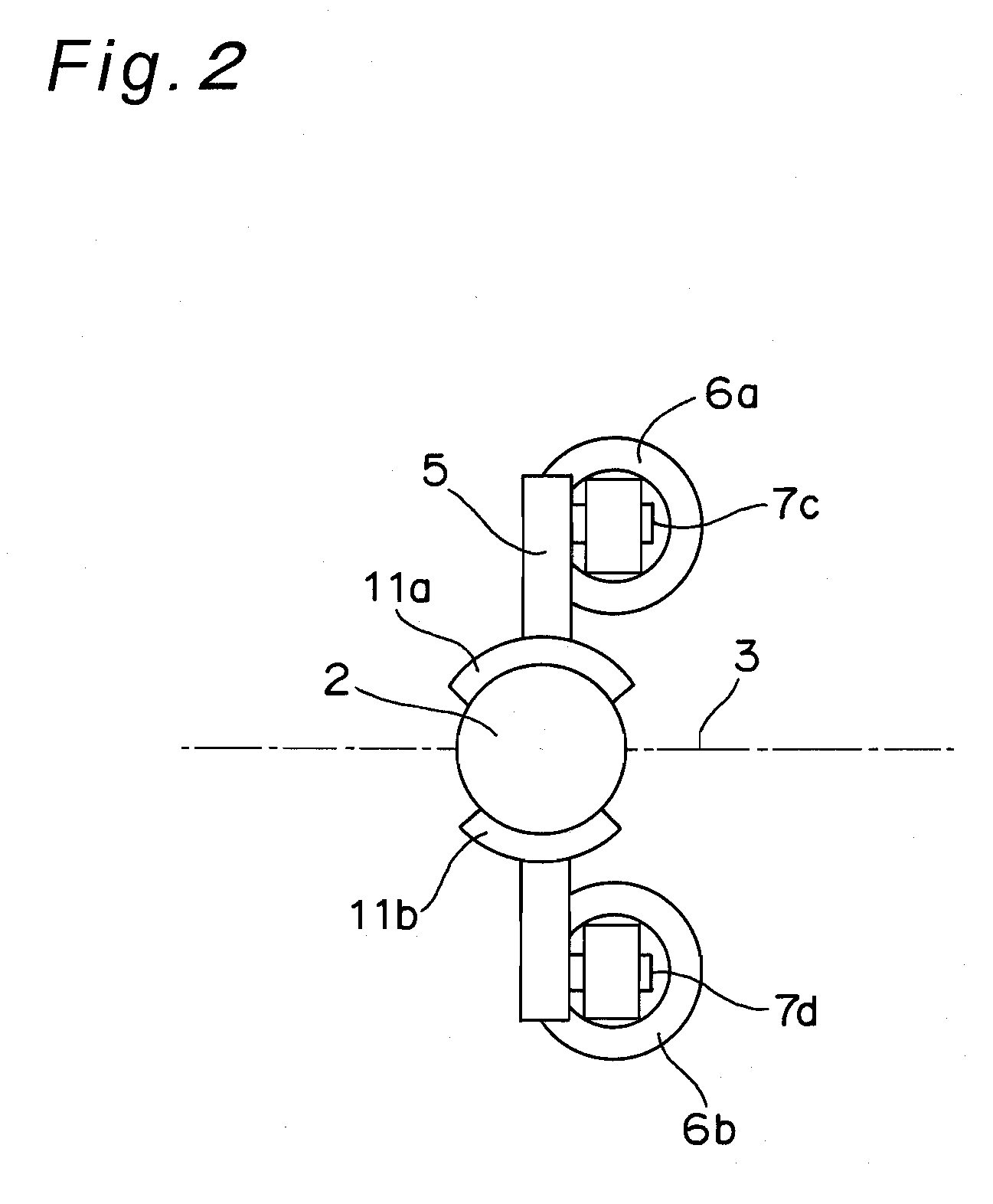
[0071]FIG. 1 is an overall view that shows a structure of a compressible fluid pressure actuator driving mechanism in accordance with a first embodiment of the present invention. In FIG. 1, reference numeral 1 represents a first structural member, and reference numeral 2 represents a second structural member. The first structural member 1 and the second structural member 2 are coupled to each other by a rotary joint 3 so as to be rotatable relative to each other. An angle sensor 70, such as an encoder, is disposed in the rotary joint 3, so that a joint angle θ made by the center axis of the first structural member 1 and the center axis of the second structural member 2 shown in FIG. 6 can be measured.
[0072]In the first structural member 1, actuator supporting members 4a and 4b opposing each other are disposed in a direction orthogonal to the longitudinal direction of the first structural member 1, and in the second structural member 2, an actuator driving-force transmission member 5...
second embodiment
[0118]FIG. 11 is a view that shows a structure of a compressible fluid pressure actuator driving mechanism in accordance with a second embodiment of the present invention. The compressible fluid pressure actuator driving mechanism of FIG. 11 differs from that of the first embodiment in the following structural components, and the other components are the same as those of the first embodiment; therefore, the same components as those of the first embodiment are given the same reference numerals as those of the first embodiment, and a detailed description thereof is not made. The second embodiment is an example in which neither the high-pressure tank 8 nor the pressure control valve 19 is provided.
[0119]In FIG. 11, reference numeral 16 denotes a bypass pipe that serves as one example of a bypass means that functions as another example of the proximate fluid pressure high-speed control means, and the bypass pipe 16 directly connects sealing members 14 to each other, which are on the res...
third embodiment
[0132]FIG. 13 is a view that shows a structure of a compressible fluid pressure actuator driving mechanism in accordance with a third embodiment of the present invention. The compressible fluid pressure actuator driving mechanism of FIG. 13 differs from that of the first embodiment in the following components, and the other components are the same as those of the first embodiment; therefore, the same structural components as those of the first embodiment are given the same reference numerals as those of the first embodiment, and a detailed description thereof is not made.
[0133]In FIG. 13, reference numerals 20a and 20b denote relief valves that are another example of the proximate fluid pressure high-speed control means, and both of the relief valves 20a and 20b are disposed near the joint 3 of the second structural member 2 and mechanistically connected to collision detecting sensor plates 38a and 38b that are formed of substantially L-shaped plate members. That is, the ends of the...
PUM
 Abstract
Description
Claims
Application Information