Liquid Phase Hydroprocessing With Temperature Management

a liquid phase hydroprocessing and temperature management technology, applied in the direction of organic chemistry, physical/chemical process catalysts, chemistry apparatus and processes, etc., can solve the problem of over-complexity of the hydroprocessing uni

Active Publication Date: 2009-12-31
UOP LLC
View PDF87 Cites 38 Cited by
  • Summary
  • Abstract
  • Description
  • Claims
  • Application Information

AI Technical Summary

Benefits of technology

[0008]A hydroprocessing reaction zone system and method of hydroprocessing hydrocarbons through that system are provided in which a hydrocarbonaceous feed of substantially liquid phase is processed throughout the hydroprocessing reaction zone. The temperatures of the process flow through the reaction zone are managed by least one internal heat transfer section positioned within the reaction vessel. In such configurations, the temperatures in the reaction zone can be effectively managed without the use of recycle gas, without additional added quench streams and, in most cases, even without additional added liquid recycle streams. The temperature controlled reaction zone further may be combined with a high pressure stream separation system to provide the further improved separation of the liquid and vapor phase of the hydroprocessed effluent. Such configurations and methods can be used to provide a compact hydroprocessing vessel and a simplified hyrdroprocessing system that includes internal temperature management control.

Problems solved by technology

Thus, the methods and systems of such aspects having a hydrogen consumption below about 500 SCF / B generally avoid having to dilute the hydrocarbon stream with diluents and other temperature control fluids, which can have undesired effects on the reactions and result in undue complexity to the hydroprocessing unit.

Method used


Image

  • Liquid Phase Hydroprocessing With Temperature Management
  • Liquid Phase Hydroprocessing With Temperature Management
  • Liquid Phase Hydroprocessing With Temperature Management

Examples


Embodiment Construction

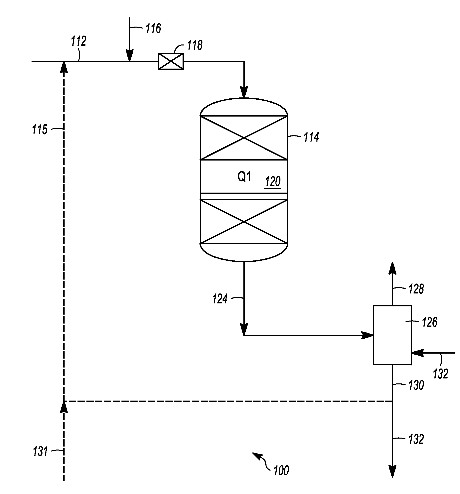
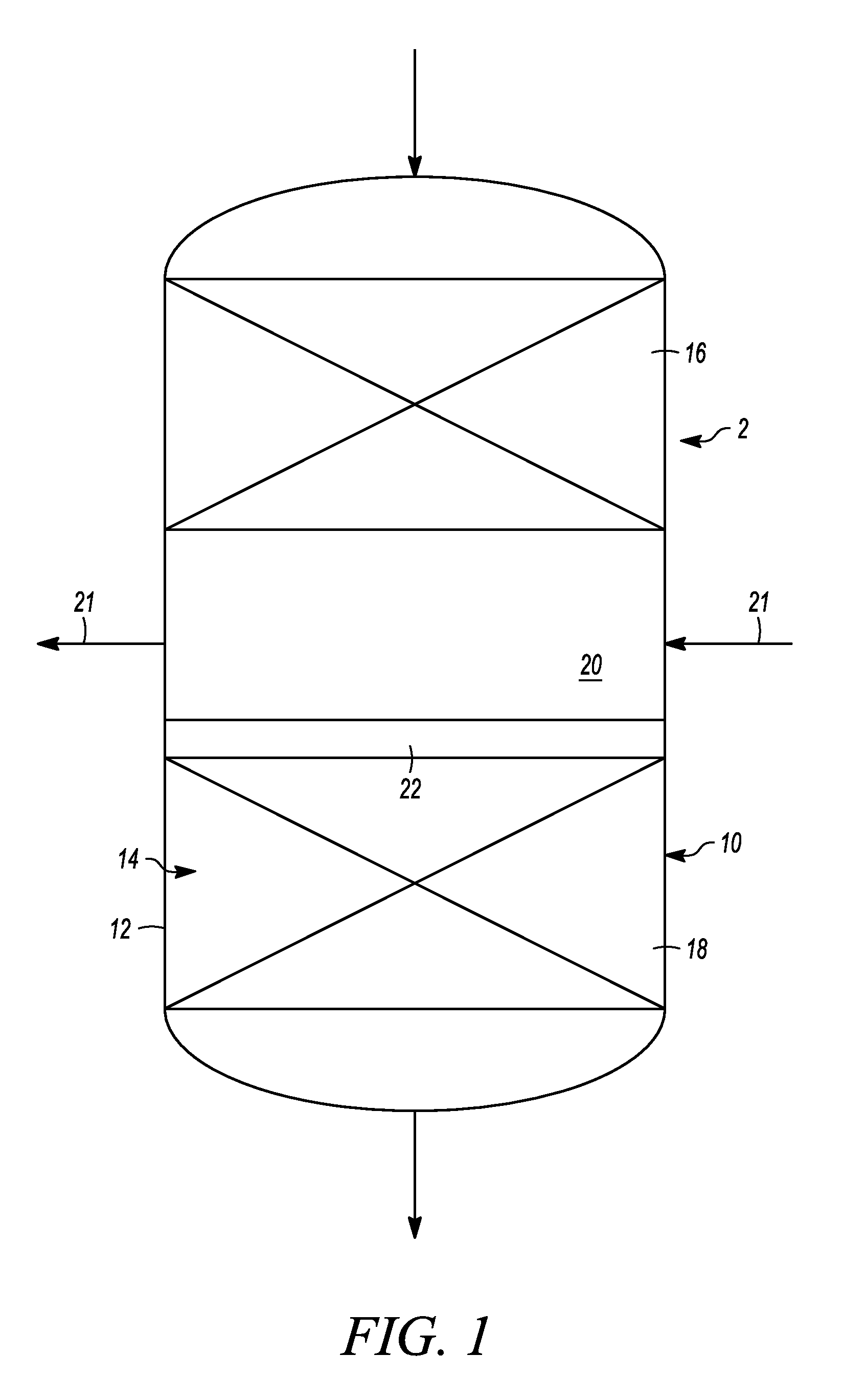
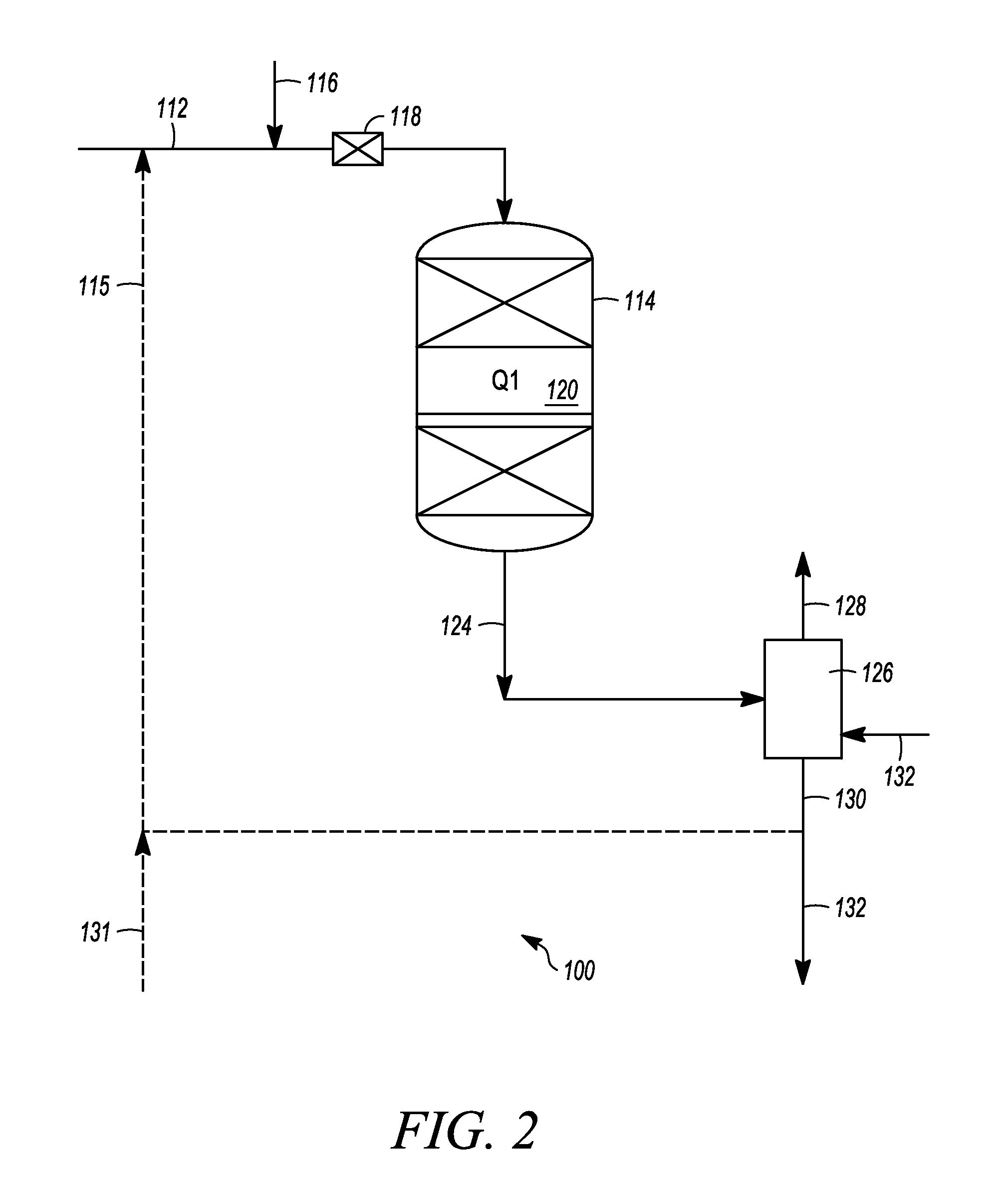
[0019]In general, hydroprocessing systems and methods described herein are particularly useful for hydroprocessing a hydrocarbonaceous feed stock containing hydrocarbons and / or other organic materials to produce a product containing hydrocarbons and / or other organic materials of lower average boiling point, lower average molecular weight, and / or reduced concentrations of contaminants, such as sulfur and nitrogen and the like. In one aspect, the systems and methods use a substantially liquid-phase reaction zone with internal temperature management that eliminates, or substantially reduces, the need for the introduction of diluents or quench streams or additional fluids into the feed stream to the reaction zone to assist in managing the temperature of the feed and reaction zone. Accordingly, the systems and methods may operate without, or may operate with substantially reduced, recycle gases added to the feed stream, recycle gas compressors, liquid quench streams, and, in many instanc...


PUM

PropertyMeasurementUnit
pressureaaaaaaaaaa
pressureaaaaaaaaaa
pressureaaaaaaaaaa

Abstract

A method of hydroprocessing hydrocarbons is provided using a substantially liquid-phase reactor having first and second catalyst beds with a heat transfer section positioned therebetween. The first and second catalyst beds and the heat transfer section are combined within the same reactor vessel. Each catalyst bed having an inlet temperature and an exit temperature and having a hydroprocessing catalyst therein with a maximum operating temperature range. The method hydroprocesses the hydrocarbons and removes sufficient heat from the hydrocarbons using the heat transfer section so that the exit temperature of the hydrocarbons existing the first catalyst bed is substantially maintained below the maximum operating temperature range of the hydroprocessing catalysts in the first bed and, at the same time, also providing the hydrocarbons to the second catalyst bed at the inlet temperature so that the exit temperature of the hydrocarbons at the exit of the second catalyst bed also does not exceed the maximum operating temperature range of the hydroprocessing catalyst in the second bed.

Description

FIELD OF THE INVENTION[0001]The field generally relates to hydroprocessing of hydrocarbon streams and, more particularly, to hydroprocessing using substantially liquid-phase hydroprocessing.BACKGROUND OF THE INVENTION[0002]Petroleum refiners often produce desirable products such as turbine fuel, diesel fuel, middle distillates, naphtha, and gasoline boiling hydrocarbons among others by hydroprocessing a hydrocarbon feed stock derived from crude oil or heavy fractions thereof Hydroprocessing can include, for example, hydrocracking, hydrotreating, hydrodesulphurization and the like. Feed stocks subjected to hydroprocessing can be vacuum gas oils, heavy gas oils, and other hydrocarbon streams recovered from crude oil by distillation. For example, a typical heavy gas oil comprises a substantial portion of hydrocarbon components boiling above about 371° C. (700° F.) and usually at least about 50 percent by weight boiling above 371° C. (700° F.), and a typical vacuum gas oil normally has ...

Claims


Application Information

Patent Timeline
Patent Type & Authority Applications(United States)
IPC IPC(8): C07C5/02
CPCC10G49/26C10G2300/807C10G2300/4093
Inventor PETRI, JOHN ANTHONYKOKAYEFF, PETER
Owner UOP LLC
Why Eureka
Try Eureka