
Rapid rotational foam molding process

Inactive Publication Date: 2010-01-07
POP ILIEV REMON +2
View PDF4 Cites 5 Cited by
  • Summary
  • Abstract
  • Description
  • Claims
  • Application Information

AI Technical Summary

Problems solved by technology

However, in addition to being extremely time consuming and very energy-intensive, due to the unavoidable thermal gradient formed across the mold during both heating and cooling, the single-charge technique suffers from difficulties of controlling the timely formation of the solid skin versus the formation of a foamed core or layer of controlled density.
This is often demonstrated through a premature decomposition of the CBA compounded into the foamable pellets, thereby causing poor skin thickness uniformity, foam invasion / protrusion into the skin, undesired coarse-celled foam morphologies and a weak skin-foam interface.
The rotational molding technology is inherently disadvantaged by very lengthy and energy-intensive processing cycles, which are even further aggravated when processing integral-skin plastic foams, due to the insulative effect of the developed foam layer or core within the mold.
Rotational molding production cycles are, undesirably, lengthy because the plastic material charged into the bi-axially rotating mold has to be indirectly heated from room temperature to beyond its melting point (which is traditionally conducted by using convection-based heath transfer while implementing an oven) and then cooled back to room temperature (which is traditionally achieved by forced airflow and / or water sprinklers) until it eventually solidifies.
In addition, the foam developed within the mold during processing produces an undesired insulative effect which slows down and practically precludes any real-time process control of both the heating and cooling segment of the cycle even further.
However, the control of the cell size of rotationally foam molded cellular structures formed based on the use of a chemical blowing agent (CBA) might be often aggravated by some inherent limitations that are unique to the rotational molding process such as lengthy processing cycles, which result in coarser-celled final cellular structures being yielded.
Although the single-charge processing concept is beneficial for improving the efficacy of the molding process and the structural homogeneity of the moldings, it certainly suffers from inherently aggravating the fulfillment of crucial processing goals such as: (i) the execution of the adhesion of the non-foamable thermoplastic resin to the internal surface of the mold that should always take place prior to the thermal activation of the foaming resin (thereby avoiding skin protrusions), and (ii) obtaining a solid skin layer with a uniform thickness.
This study clarified why in rotationally foam molded cellular structures based on the use of a CBA, a fine-celled morphology has been closely approached, but it has not been actually achieved yet.
Thus, it was clearly indicated that it would be very difficult to generate the preferred kind of bubbles (fine-celled) in rotational foam molding unless the duration of the heating portion of the process is dramatically reduced, or else.
Particularly, very limited research has been conducted on the processing of integral-skin cellular polymeric composites in rotational foam molding, while even a smaller body of literature deals with the study of the single-charge rotational foam molding technology.
Furthermore, while several authors have done an admirable job in studying the formation and removal of unwanted bubbles in conventional rotational molding, other than a few recent studies, no substantial work has been performed yet to explain the mechanisms governing the CBA-blown production and retention of controlled size bubbles and their lifespan in non-pressurized non-isothermal polymer melts, such as in rotational foam molding.
Likewise, compared to PE foams, very little research has been accomplished to date on the production of PP foams in rotational foam molding.

Method used


Image

  • Rapid rotational foam molding process
  • Rapid rotational foam molding process
  • Rapid rotational foam molding process

Examples


Embodiment Construction

[0031]The basic rationale of the embodiments of the present invention is that it would be desirable to decouple the heating segment of the rotational molding process by using a much more efficient plastic fabrication method such as, for example, extrusion. Extrusion is a fundamental shaping and compounding process for polymers.

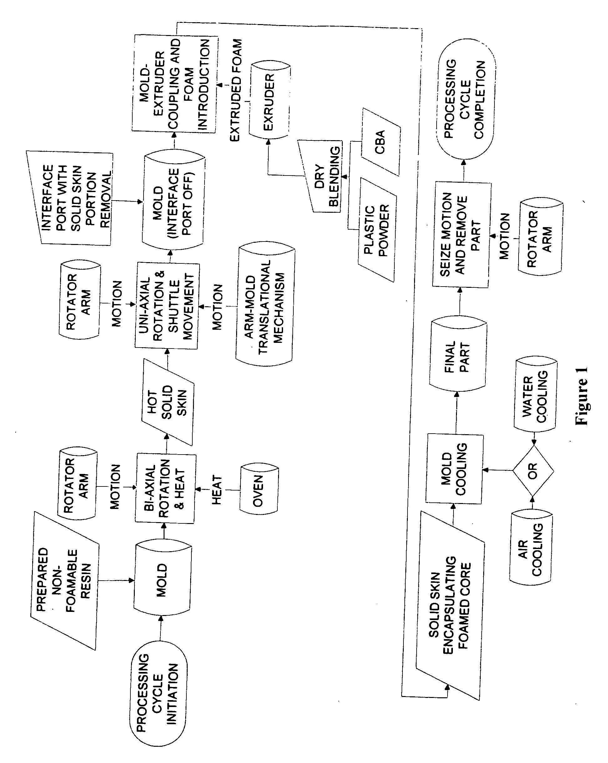
[0032]The flow of the process for extrusion-assisted uni-axial and biaxial rotational molding is shown generally at 100 in FIG. 1. The process can be explained in the following steps:

[0033]First the mold 102 is opened and the non-foamable plastic resin 104 is added.

[0034]The mold 102 is resealed and the rotational arm 106 begins to rotate bi-axially 108.

[0035]The rotating arm is moved into the oven 110 and sealed. Using the proper heating rates and temperature profile the non-foamable plastic is melted. Once melted, the polymer is evenly distributed about the mold because of the motion induced. The skin 112 has, as a result, been created.

[0036]The mold, while ...


PUM


Abstract

The nature of the rotational molding process is cyclic. It requires the temperature of the rotating mold and the plastic it is charged with to be elevated from room temperature to beyond its melting temperature and then cooled back to room temperature. Consequently, rotational molding cycle times are lengthy, which is often considered as the fundamental drawback of this plastic fabrication process. The motivation and objectives of this disclosure are twofold. The presently proposed invention focuses on developing an innovative extrusion-assisted rotational foam molding processing technology for the manufacture of integral-skin cellular composite moldings having adjacent, but clearly distinct, layers of non-cellular and cellular structures, consisting of identical or compatible polymeric grades. Its primary goal is to significantly reduce the processing cycle time in comparison with respective currently implemented technologies by employing melt extrusion in order to maximize the speed of controlled polymer melting.

Description

CROSS REFERENCE TO RELATED PATENT APPLICATION[0001]This patent application relates to United States Provisional Patent Application Serial No. PCT / CA2008 / 00814 filed on May 1, 2008, designating the United States and entitled EXTRUSION ASSISTED ROTATIONAL FOAM MOLDING PROCESS which is incorporated herein by reference in its entirety.FIELD OF THE INVENTION[0002]This invention relates to a rotational foam molding process and in particularly an extrusion assisted rotational molding process which exploits the synergistic effects resulting from the deliberate conjunction of extrusion with rotational molding. The process is well suited for speedy processing of polymeric integral skin rotational foam moldings and is referred to as Rapid Rotational Foam Molding.BACKGROUND OF THE INVENTION[0003]Rotational foam molding has lately been brought into being a distinct plastic processing technology. It has been developed by deliberately modifying the conventional rotational molding process to accomm...

Claims


Application Information

Patent Timeline
IPC IPC(8): B29C41/04B28B21/32
CPCB29C41/04B29C44/0461B29C41/36B29C41/22
Inventor POP-ILIEV, REMONCHRISTIAN, KIMBERY ANNEABDALLA, EMAD SAMY
Owner POP ILIEV REMON
Learn More