
Battery System

a battery system and battery technology, applied in the field of battery systems, can solve the problems of exceeding the difficulty of increasing the withstand voltage of the integrated circuit, etc., and achieve the effects of improving the reliability of the battery system, high accuracy, and accurate state detection of lithium ion battery cells

Active Publication Date: 2010-01-07
HITACHI LTD +1
View PDF10 Cites 77 Cited by
  • Summary
  • Abstract
  • Description
  • Claims
  • Application Information

AI Technical Summary

Benefits of technology

[0011]The present invention intends to provide a highly reliable battery system.
[0029]According to the present invention, reliability of a battery system can be improved. A great advantage can be achieved, for instance, when the present invention is applied to a lithium ion battery system. More specifically, an enormous advantage can be achieved when the present invention is applied to a lithium ion battery system for vehicles.
[0030]For a lithium ion battery system, it is desirable to constantly monitor the state of lithium ion battery cells with high accuracy based upon detection by a lithium ion battery cell controller. If a part of the lithium ion battery cell controller is damaged, accurate state detection of lithium ion battery cells, diagnosis based upon detection result, or information transmission may be difficult. In addition, the lithium ion battery cell controller may transmit an incorrect detection result or an incorrect judgment result that causes an erroneous operation. It is desirable to prevent these problems. Occurrence of the above-described problems may endanger human lives, particularly in a vehicle lithium ion battery system, therefore safety is desired to be improved. In addition, since a vehicle moves and subsequently has a possibility to encounter an accident, the accident may cause damage in the circuits. This results in a desire for high safety in a vehicle lithium ion battery system. Furthermore, since a vehicle lithium ion battery system is likely to be used in a variable environment for a long period of time, high safety is desired from this point of view as well.

Problems solved by technology

It is difficult to increase withstand voltage in these integrated circuits.
If a high voltage is applied to the integrated circuits for some reasons, it exceeds the withstand voltage of the integrated circuits and they may be damaged.

Method used


Image

  • Battery System
  • Battery System
  • Battery System

Examples


Embodiment Construction

[0051]Embodiments described below achieve improvements in various points desirable for manufacturing, i.e., not just improvement in reliability but also in other points. Representative points and their solutions will now be described.

[0052][Uniformity with Regard to Power Consumption at Battery Cells]

[0053]An effort is made for the invention explained below so as to prevent the power consumption at serially connected lithium ion battery cells mounted on vehicle from becoming imbalanced. That is, uniformity is achieved with regard to the power consumption related to the lithium ion battery cells mounted on vehicle, in other words, electric power load of the lithium ion battery cells. Although descriptions below present a particularly effective example, in which the present invention is mounted on a vehicle, the present invention is not limited to be mounted on vehicles such as an electric train or an automobile. An advantageous effect can be achieved by applying it to an industrial b...


PUM


Abstract

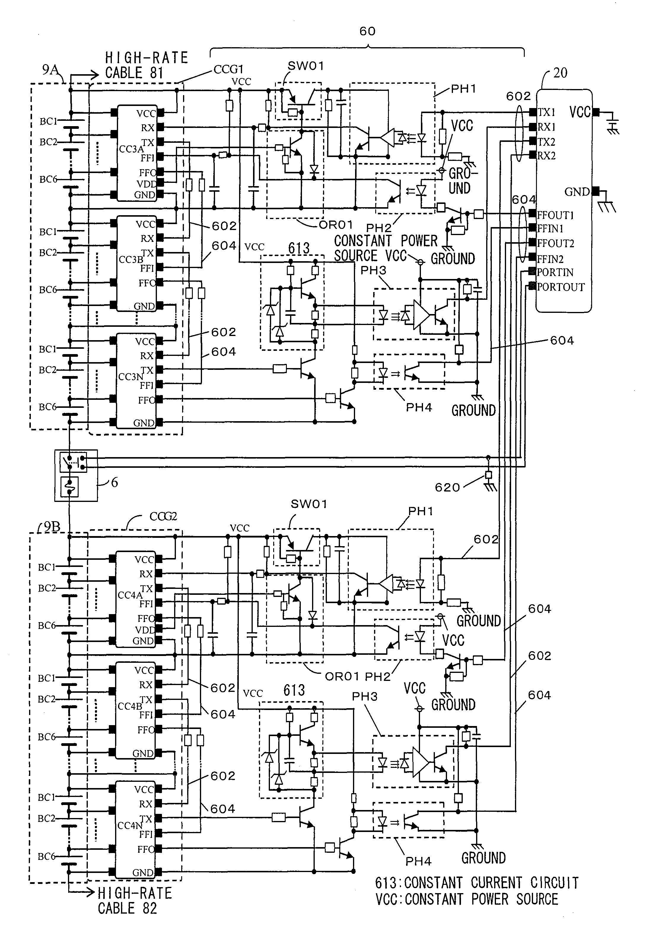
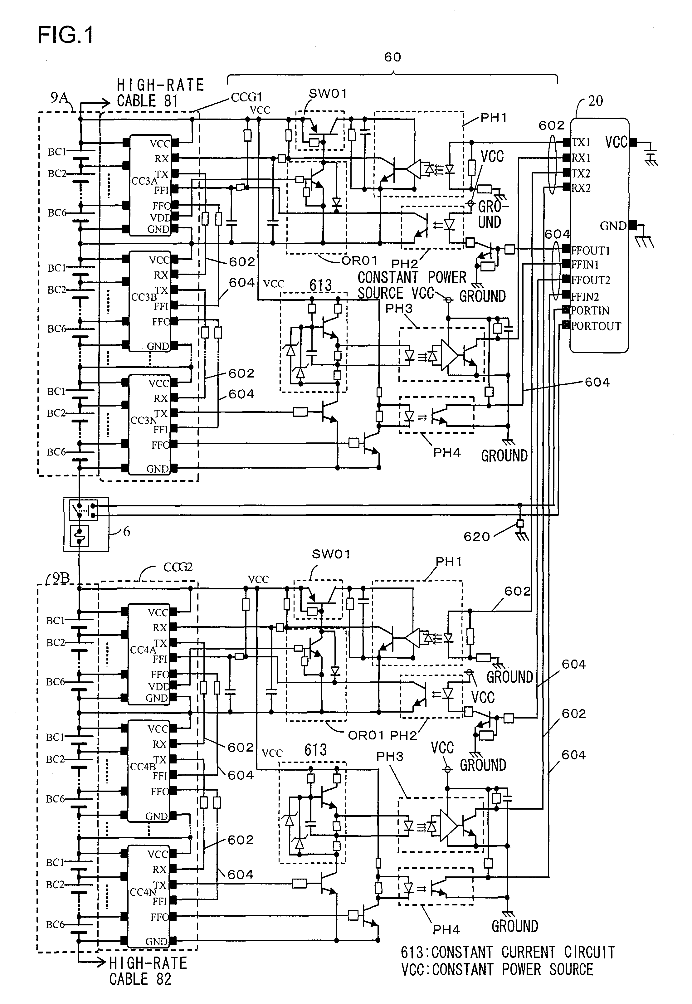
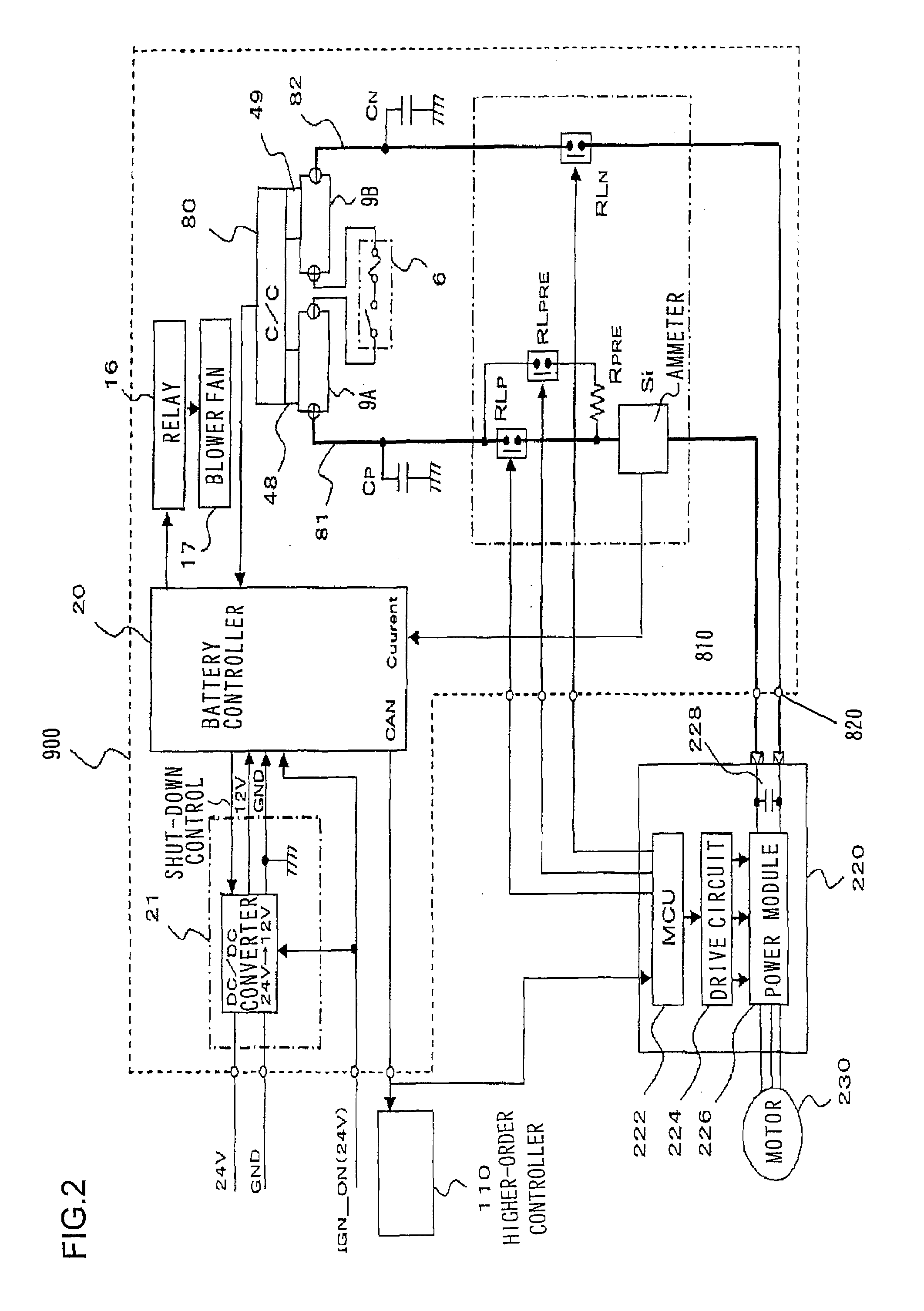
A battery system includes a battery module that is constituted with a plurality of serially connected battery cells, a plurality of integrated circuits that group the battery cells by a plurality thereof so as to perform processing on battery cells in each group, a first transmission path through which a command signal is transmitted via a first insulating circuit from a higher-order control circuit that controls the plurality of integrated circuits to a highest-order integrated circuit of the integrated circuit, a second transmission path through which a data signal collected by the plurality of integrated circuits is transmitted from the highest-order integrated circuit to a lowest-order integrated circuit, and a third transmission path through which the data signal is transmitted from the lowest-order integrated circuit to the higher-order control circuit via a second insulating circuit.

Description

INCORPORATION BY REFERENCE[0001]The disclosure of the following priority application is herein incorporated by reference:[0002]Japanese Patent Application No. 2008-172477 filed Jul. 1, 2008BACKGROUND OF THE INVENTION[0003]1. Field of the Invention[0004]The present invention relates to a vehicle battery system used for a vehicle having an electric drive such as an electric vehicle, a hybrid vehicle, and an electric train, or a general industrial power supply system. In addition, the present invention relates to a circuit board and an integrated circuit for these systems.[0005]2. Description of Related Art[0006]As Japanese Laid Open Patent Publication No. 2003-70179 discloses, a conventional battery system includes a battery module constituted by connecting a plurality of battery groups which are constituted by serially connecting a plurality of battery cells, and subordinate control devices that individually monitor the state of the battery cells for each of the battery groups. These...

Claims


Application Information

Patent Timeline
IPC IPC(8): G01N27/416B60K6/28H01M50/51H02J7/02
CPCB60L11/18H01M6/42H02J7/0013H02J7/0016B60L2200/26Y02T10/7005Y02T10/7011Y02T10/7055H02J7/0021G01R31/396B60L50/64H02J2310/48Y02T10/70H02J7/0048H02J7/0014H02J7/0047H02J7/0019H02J7/00034
Inventor KUBO, KENJIKUDO, AKIHIKOKIKUCHI, MUTSUMISHIBAHARA, GOSUKE
Owner HITACHI LTD
Learn More