Rfog modulation error correction

a technology of rfog modulation and error correction, applied in the direction of speed measurement using gyroscopic effects, instruments, surveying and navigation, etc., can solve the problems of insufficient method accuracy for rotation sensing rotation sensing error

Active Publication Date: 2010-01-07
HONEYWELL INT INC
View PDF0 Cites 21 Cited by
  • Summary
  • Abstract
  • Description
  • Claims
  • Application Information

AI Technical Summary

Problems solved by technology

However, this method is not accurate enough for rotation sensing and thus another more precise method is needed.
There are imperfections in the gyro that will cause an error in detecting the resonance frequency, thus an error in rotation sensing.
There are two types of modulator imperfections that can result in rotation sensing errors.
The deviation away from the resonance frequency results in a rotation sensing error if the unwanted intensity signals are different between the two counter-propagating light waves.
Another modulator imperfection that can result in rotation sensing errors is modulation distortion.
The modulation distortion can occur at the modulator drive electronics or the modulator.
However, distortion can result in the generation of higher harmonics on the modulation.
Even harmonic modulation will result in a resonance detection error which can lead to a rotation sensing error.
One drawback to common modulation is the gyro system becomes sensitive to other imperfections associated with optical back-reflection or backscatter within the resonator.
Backscattered light will result in two types of errors.
One type of error (interference-type) is associated with the optical interference between the backscattered wave and the primary wave that reaches the photodetector.
The disadvantage of employing independent modulation of the counter-propagating light waves is that modulator imperfections are no longer cancelled out through common mode rejection.

Method used


Image

  • Rfog modulation error correction
  • Rfog modulation error correction
  • Rfog modulation error correction

Examples


Embodiment Construction

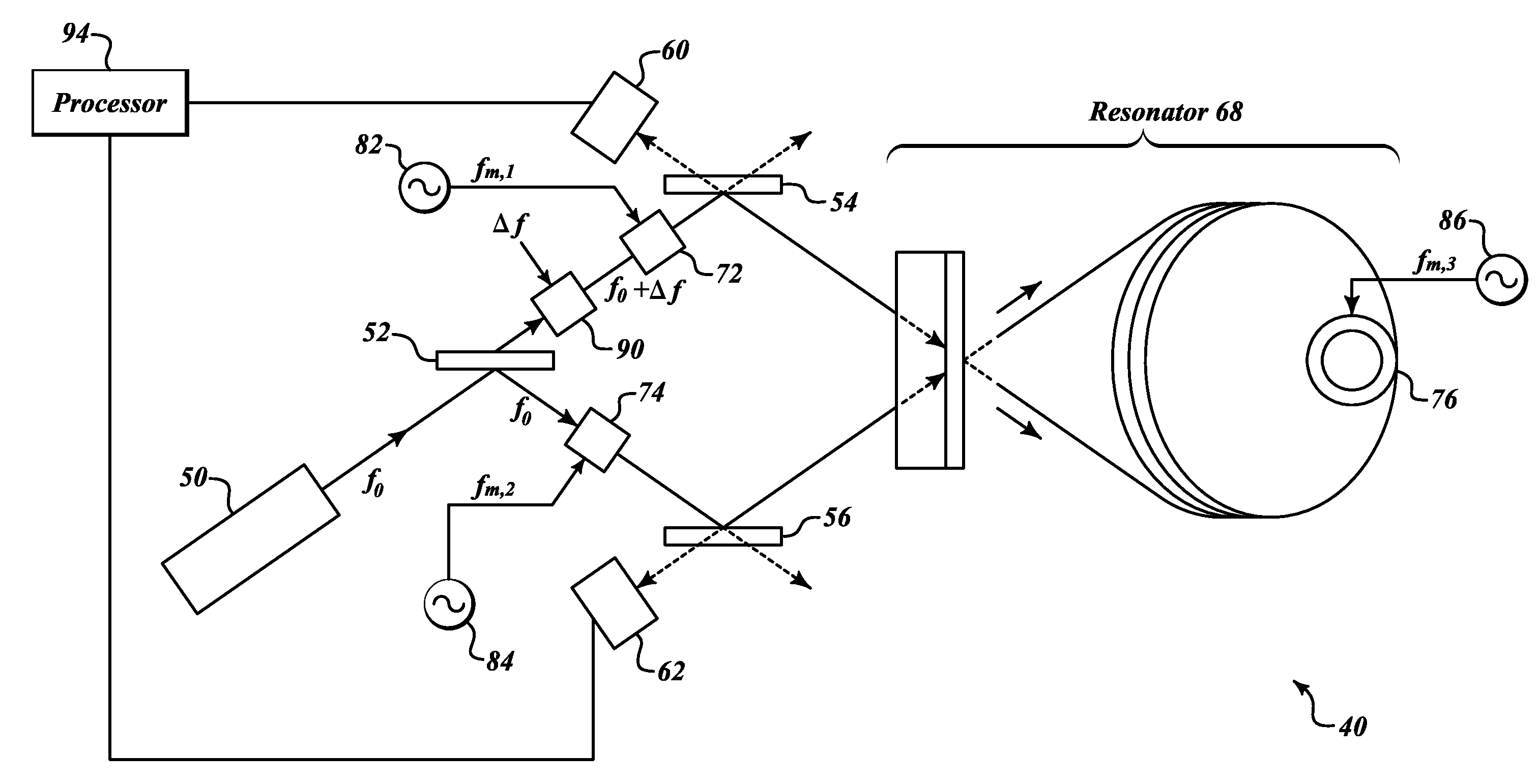
[0022]FIG. 8 shows an embodiment of the present invention that eliminates rotation sensing errors due to modulator imperfections and backscatter. An RFOG 40 includes a light source 50, beam splitters 52-56, photodetectors 60, 62, a resonator 68, modulators 72, 74, 76 with associate modulation generators 82, 84, 86, a frequency shifter 90, and a processor 94.

[0023]A common cavity length modulator 76 performs resonance detection and eliminating errors due to modulation imperfections. Cavity length modulation can be performed by a piezoelectric tube wrapped with resonator fiber, or a piezoelectric element placed on a resonator mirror. Independent intensity modulation (the intensity modulators 72, 74) of the two counter-propagating beams is used for encoding each light wave with a unique signature such that unwanted intensity signals due to backscatter can be rejected by signal processing. The frequencies of the intended intensity modulation are made different and not harmonically relat...


PUM


Abstract

Systems and methods for performing modulation error correction. An example system applies common phase / frequency modulation to first and second laser beams, a first intensity modulation to the first modulated beam, and a second intensity modulation to the second modulated beam. Signals outputted are demodulated according to the frequency of the common phase / frequency modulation. Then the first of these demodulated signals is demodulated based on the frequency of the intensity modulation of the first beam, and the second of these demodulated signals is demodulated based on the frequency of the intensity modulation of the second beam. Then, rate of rotation is determined based on demodulated signals. Frequencies of the intensity modulations are unequal and not harmonically related, and intensity modulation encodes each light beam with a unique signature.

Description

PRIORITY CLAIM[0001]This invention claims the benefit of U.S. Provisional Application Ser. No. 60 / 948,352 filed Jul. 6, 2007, the contents of which are hereby incorporated by reference.BACKGROUND OF THE INVENTION[0002]The resonator fiber optic gyro (RFOG) senses rotation by detecting the frequency difference between clockwise and counterclockwise resonance frequencies of a fiber optic resonator. The resonance frequencies of the fiber resonator are probed with a narrow band laser or lasers. The resonator translates an optical frequency to an optical intensity. For example, for the reflection resonator as shown in FIG. 1, the light intensity detected by the photodetectors will be maximum when the optical frequency is away from the resonance frequency. However, when the optical frequency approaches the resonance frequency, the light intensity sharply dips to a minimum at the resonance frequency. Therefore, one method to detect the resonance frequency is to detect the minimum power at t...

Claims


Application Information

Patent Timeline
Patent Type & Authority Applications(United States)
IPC IPC(8): G01C19/72
CPCG01C19/727
Inventor STRANDJORD, LEE K.SANDERS, GLEN A.
Owner HONEYWELL INT INC
Why Eureka
Try Eureka